Hello, I am using a pair of GU50's in place of KT66's in my homemade QUAD II amp. The output transformer is an original Quad. The only extras (apart oil caps in place of the TCC electrolytic) is a string of 2 voltage regulator tubes that set the screen voltage to approx 300V. In series and very close to anode pins I put 33R small resistors that helped to eliminate a small oscillation that appeared before clipping. The output power is approx 19W sine continuous @ 15 Ohms. This is driving an LS3/5a as a center channel in my home cinema.
Just connect G2 to the anode with 100 ohm and g3 to the cathode?
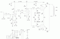
The attached file is the schematic of a Chinese Amplifier which I bought last year.
G2 is connected to Plate via 200ohm. Plate voltage is 520V.
G3 is not described in this schematic but it is connected to the Cathode
in the datasheet.
Attachments
Strange Schema
Hello,
I'm interested in constructing a GU50 PP amp and I discovered this thread to gather some ideas. Has anyone constructed one and what are the best drivers for this?
I would be prudent in believing that schema.
I would also verify if you actually have a choke for the driver stage. The chinese like to indicate choke but give you a nice military res instead.
What is the voltage on the grid and where's the power supply for it?
- Status
- This old topic is closed. If you want to reopen this topic, contact a moderator using the "Report Post" button.
