I just read this design idea on the tubecad site: http://www.tubecad.com/march99/page6.html
This should increase damping factor without risk for oscilations.
I think there are some drawbacks however:
- If using the capacitor/resistor shelving filter, the gain at mid/high frequency is lowered.
- I think one disadvantage of negative feedback is still present: harsher clippping.
Did anyone tried this to expand the frequency response and get a good damping factor from cheap transformers?
Thanks for that link - very logical and most interesting, I must try modeling it. It seems that this could be an especially useful technique for pentode OP stages. Although NFB is necessary at all frequencies with pentodes (unless one finds high order distortion appealing), it is much more strongly required in the bass than in the middle and treble, since that is where the poor electrical damping of pentodes is most apparent.
Svokke,
I am not one of the believers in the disadvantages of NFB in proper designs, which is not at all difficult. A damping factor of more than 20 - 30 is not going to cause any further improvement. You correctly state that harsh clipping can be one disadvantage of NFB. But that is not where one normally listens; for me it is a question of having lower distortion all the time vs. having less harsh clipping some of the time.
There were circuits using this, like a classic design by a well-known British designer of the time (40s - 50s), Noël Bavaria-Hunt (I am the proud possessor of a letter from him explaining certain matters). But it is a rather cumbersome affair with a huge choke, etc.
You ask about a good damping factor from a cheap transformer. I would rather use the combined neg-pos. feedback circuit described by John Miller in an Electronics Engineering Manual published by McGraw-Hill in the 50s, but this is not of much help; I have no idea of its origin. (He was with Bendix Radio Division in Baltimore, Maryland.) He used a dirt-cheap output transformer to get well under 1% distortion.
The principle is that you apply positive feedback round all but the power stage, and global negative feedback. If one increases the positive feedback to nearly the oscillation point, the negative feedback will off-set it and in the limit the output stage influence disappears. That is theoretical of course, but it makes a substantial difference in practice (I did build the circuit at the time, using 6V6 output tubes driven by a 6SN7). The only penalty is a few extra resistors and capacitors to take care of the phase.
The circuit diagram in the book is quite small but I will try to have it scanned and post it, even if only to illustrate the idea. [Note that this is not current (motional) feedback from the loudspeaker, which is also a type of neg-pos. feedback circuit, which can also offer very good loudspeaker control.]
Regards
Variable feedback using a shelving filter (aka Broskie's TCJ) may be difficult to implement. Case in point:
The output stage of my SE KT88 (triode configuration) uses local feedback that encompasses the driver, power tube, and output transformer. Open loop gain is 3.9V/V. The driver stage must apply 7.6Vp-p to the grid of the KT88 to achieve 1Vp-p output from the transformer. Obviously, these numbers are a result of the driver tube, the KT88, and the output transformer winding ratio.
When I apply the output stage's local feedback loop, the gain drops down to .79V/V, which is under unity gain. The driver still needs to apply 7.6Vp-p to the KT88's grid for 1Vp-p output.
Using simulation, the Broskie's variable feedback shelving filter was applied in the driver section (inside of the output stage's local feedback loop, as he recommends in the March 99 blog). I used a 1:3 ratio of F1:F2, R1/R2 = 3, R1 = 60k, R2 = 20k, F2 = 120Hz, C = 0.068uF (which actually results in F2 = 117Hz).
Because of the loss through the shelving filter at higher frequencies (i.e. 1kHz), the closed-loop output stage gain drops to 0.42V/V, requiring 32.7V from the driver stage. This is a 4 times increase of demand on the driver stage to overcome the losses of the shelving filter and drive the output to 1V! Yipes!
Since the driver section can handle about 80V p-p swing before clipping, this only amounts to about 2.4V at the output, or 0.75 Watts into 8 Ohms when the driver stage is maxed out!
Building a driver stage that can handle larger voltage swings get difficult. This requirement is much harder than driving a 300B. With this logic, the driver stage would need 292V swing to get 10 watts of output.
I found this to be an intriguing idea, however the realities of the votlage losses incurred by the shelving filter puts a big demand on the driver stage.
How to fix this? I also tried a high-gain output tube (KT88 in pentode mode). This drops the driver stage requirement down to 20V to get 1V of output. Supplemental gain stages could also work, but then you would be adding more distortion-creating parts to create the gain you need to get feedback to reduce distortion. Go figure.
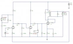
OK, so I was curious about this variable feedback phenomena, so I spent some time simulating the circuit in the March 99 TCJ blog.
I simulated both driver valves as the 12AU7 and the output KT88 in triode mode with 400V power supply. The OPT had a 312 impedance ratio (primary to secondary) with a 400 Ohm primary, based on a Plitron specification. The first 12AU7 had 660 Ohm cathode resistor and 80k plate resistor for 3.78mA. The second 12AU7 had 30k cathode resistor and 75 plate resistor for 3.27mA. The output of the second triode was centered on 154V. The KT88 was running 82.5mA through a bypassed 400 Ohm cathode resistor (self bias).
Open loop (no feedback), the gain was 7.91V/V. The KT88 grid was driven to 27.5V, which means the driver needed to produce 3.5V for every 1V at the output.
Feedback was applied using cathode feedback. The cathode resistor of V1 was connected through the OPT secondary. The gain dropped to 0.846V/V with 2.976V on the KT88 grid. This means the driver needs to produce 3.5V for every 1V on the output. Nice enough.
The output stage can drive up to about 14V into the load (assuming the OPT parameters and 8 Ohm load). This may not be optimized, but I didn’t spend the time tweaking it.
I used a shelf filter for variable feedback of 1:3 ratio using 60k/20k resistors and 0.068uF capacitor for 117Hz frequency for F2. The gain dropped to 0.619V/V with 3.97V required on the output of V1. This means V1 must swing 6.4V for every 1V on the output.
To get 14V on the output (maximum power), V1 must swing 89.6V. This actually doesn’t occur because things start compressing. The simulations show V1 starts clipping near ~80Vp-p, which makes sense, because the plate of V1 is centered a little above 100V. At this point the output is ~11V, which is underutilizing the output stage. Now the exercise becomes extending the voltage swing of V1 (and therefore also changing the center point of V2). I prefer amplifier designs with the input/driver stage having slightly more dynamic headroom than the output stage, so the output is driven into clipping before the driver stage.
Conclusion: still not worth implementing variable feedback with this particular topology. It taxes the driver stage too much. In effect, taking from Peter to pay Paul. The shelving filter costs too much, and robs too much voltage. V1 has to work twice as hard to compensate. For a “first watt” amplifier, this may be an exceptional design, but it will be driven into clipping too easily. The clipping will be nasty, too, coming from the driver stage.
Next post will be trying “ordinary” feedback, rather than this cathode feedback method.
Attachments
OK, so here's the scoop.
The shelving filter is lossy for frequencies above F2. Therefore, the driver stage must work harder to overcome the losses.
Since (essentially) no feedback is employed above F2, the amplifier is feedback free, except for the bass.
So the driver has to work extra hard to push past the shelving filter, and no feedback is offered. In my simulations, distortion is increased above F2, sometimes up to 2 orders of magnitude. Granted, simulations are not accurate for distortion, but usually within an order of magnitude.
Therefore, my study concludes variable feedback is not a benefit, because the driver stage creates much more distortion overcoming the shelving filter at frequencies above F2 that are not corrected by feedback. Overall, the amplifier can exhibit 10 to 100 times more distortion than without the shelving filter.
K.
Kashmire said:Supplemental gain stages could also work, but then you would be adding more distortion-creating parts to create the gain you need to get feedback to reduce distortion. Go figure.
Quite so, but one must be careful here. Usually most of the distortion is generated in the power stage. If an extra gain-stage is added early in the circuit where the signal level is low, the distortion it adds will be small compared to the total distortion. But it's gain would reduce the total distortion by exactly that amount, i.e. a nett gain (reduction) in total distortion figure.
This is the one advantage of global NFB compared to nested (i.e. per stage), generally speaking. In the output stage with highest distortion one would logically need most nested feedback, but that is the very point where one cannot have that because of the then unrealistic demands on the driver stage.
Understood. Yes and no.
In this case, I was looking at how much voltage was needed in the intra-gain stage (nested in the feedback and before the shelving filter). I was needing nearly 100 volts p-p swing to drive a single K88 connected in triode mode. This isn't easy for most gain stage designs to do linearly. Much of this voltage was lost in the shelving filter.
One solution is to wire the KT88 in pentode mode to reduce the demands of the driver stage, but the distortion of the output stage shoots up.
Ugh!
It does help with frequencies below F2. The shelving filter doesn't attenuate the intra-stage signal, all of the nested stages have an easier job, and the global feedback loop working at full the dB of regenerative feedback.
Above F2, the global feedback is mostly ineffective, the driver stage has to work twice as hard, and you'll distort one way or the other (either drive or output). It's never good to attenuate your signal and pile on the gain to compensate for the losses. This seems like a losing proposition.
So, yes and no: Yes, it helps below F2. No, it wreaks havoc above F2.
Don't you love inserting stuff into feedback loops? All the math changes ...
- Status
- This old topic is closed. If you want to reopen this topic, contact a moderator using the "Report Post" button.
- Home
- Amplifiers
- Tubes / Valves
- Variable feedback to enhance damping factor at low frequency