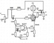
I did some N.feedback and it sounds nice.
The bass gets tighter and the voices really sound. But the tube sound remains.
Total amplification is now 1,76x.
The bass gets tighter and the voices really sound. But the tube sound remains.
Total amplification is now 1,76x.
Attachments
Last edited:
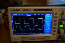
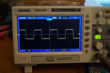
The 100k pot's source impedance and the higher gain +Miller when open loop surely makes a 11kHz range square slower vs using feedback. On 20k - 50k pots its better. Not a concern in your case, you have feedback now. Is there any ringing on the leading edge if you zoom in on the yellow trace?
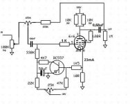
Do you really need the fix bias scheme? Did you end up choosing a really different operating point than the circa 22mA original for auto bias with the 680Ω Rcathode?
Do you really need the fix bias scheme? Did you end up choosing a really different operating point than the circa 22mA original for auto bias with the 680Ω Rcathode?
Thank you Salas for the feedback.
I am a member of a Dutch forum.
We have developed a bias machine for PP amplifiers with a number of people.
I wondered if it would also work for triode circuits.
This circuit remains stable.
And yes I can now easily set a different work point if I wanted to.
But at 22/23 mA it sounds good.
On the scope photo, the yellow is the signal input.
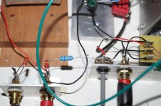
So just for the pleasure of building, I post it here.
The next step would be to put your HV shunt in between and listen what it brings.
I am a member of a Dutch forum.
We have developed a bias machine for PP amplifiers with a number of people.
I wondered if it would also work for triode circuits.
This circuit remains stable.
And yes I can now easily set a different work point if I wanted to.
But at 22/23 mA it sounds good.
On the scope photo, the yellow is the signal input.
So just for the pleasure of building, I post it here.
The next step would be to put your HV shunt in between and listen what it brings.
Thanks for your info. Since the blue trace is the output and not a comparison between FB/NoFB channels as I thought, it indicates some roll off. Even below 20kHz maybe. But you can find exactly by increasing the gen's sinus frequency until the 6V6's output signal falls 0.707 from 1kHz (-3dB).
To increase bandwidth do try with a lower value log pot also. At max volume all pots will present the same bandwidth though because they effectively go out of circuit then.
To increase bandwidth do try with a lower value log pot also. At max volume all pots will present the same bandwidth though because they effectively go out of circuit then.

Hello,
Post #144 on page 15 has a circuit I’m interested in.
I have two questions:
1. Can the pot simply be omitted if it’s going to be driven by another preamp?
2. The schematic shows no plate resistor. I’ve tried looking up calculating plate resistors for cathode followers but find very little. I’ve seen some CF circuits without them all together.
How do I calculate the value of the plate resistor.
Thanks
Thank you,
And no bypass cap is needed on the plate as well I take it? I couldn’t find any CF examples with a bypass cap. They just look like the power supply output directly into the plate from what I find.
Thanks
Forget the plate, CF works turned on its head. Playing at the cathode side. No bypass at the cathode load resistor is used because there is no local feedback degeneration voltage gain loss portion to retrieve like it would in common cathode. Local feedback is already 100% on purpose. Voltage gain is bit less than unity due to not perfect efficiency maybe 95% but output impedance is much better (lower). No signal phase reversal at the output as well.
Someone had used the common cathode version for driving that amp in the past I think. It will be a combination that behaves like having a power amp with 15dB gain. Judge if that is enough regarding your sources voltage output and your speakers sensitivity. Phase inverting also but you can connect the speakers in reverse polarity to compensate for that.
Cathode Follower Questions
I've begun sourcing some parts for this preamp and have some VERY basic questions.
1) What exactly does a or this cathode follower circuit do?
1a) What are the advantages and disadvantages of this type of circuit?
2) Is there a benefit to adding a Cathode Follower stage to the Common Cathode version?
Thanks in advance for helping a noobie out!
Although I’m sure Salas will answer your question much better than I, the point of the 6V6 line stage is that it’s not a follower, and the reason it uses a power tube in a line stage is because the output impedance right off the plate is low enough to be used directly. It’s a single stage amplifier that has ability to drive all by itself. (I.E., without a follower in addition) That is actually quite rare when using tubes.
Member
Joined 2009
Paid Member
Well said. Only remember Common Cathode is phase inverting. That can be remedied by reverse polarity connecting the speakers. When just needing unity gain the cathode follower (buffer) version of this pre is very nice sounding also. Non phase inverting in this case.
but is the cf version sound as nice as the cc version ? - it is an age old question and perhaps this preamp finally tells us the truth
You can't really say if the system chain gain isn't appropriate for each. With same amp of variable sensitivity, switch for 15dB difference, you could run them head to head and tell. CF version is quieter for microphonics due to lack of gain and this can be an advantage when sorting out between this size tubes.
- Home
- Amplifiers
- Tubes / Valves
- 6V6 line preamp