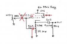
Ok, is 200V ok on those FT-3 input caps, or do I need to go 600V. Size is a bit of a concern.
Prices not bad on them on eBay.
Prices not bad on them on eBay.
FT-3 is Russian teflon capacitor. 180R/5W , 470/2W and 5K/10W (2x10k/5W).
I borrowed from a friend a 4.7uF Mundorg capacitor. Is it OK to try?
PS. Hum is gone. Bad ground wiring.
I borrowed from a friend a 4.7uF Mundorg capacitor. Is it OK to try?
PS. Hum is gone. Bad ground wiring.
Good news about solving your hum. If you mean 4u7 in the output position, that's also legit. When you want same bass and upper bass "feel" between systems calculate the RC time (translates to frequency) of your output cap and next stage's input load (each system's poweramp) to be roughly comparable in phase shift.
RC High-pass Filter Design Tool
Two words and from me. Ever since I finished this construction never came down from my audio system....
6V6 Salas (Buffer version) on Vimeo
Nikos, nice video presentation, once again congratulations on your first but thorough tube preamp build.
I think that design change would put the grid at at more than -200v relative to the cathode. With rather tragic consequences.
Built as is, the cathode follower version is quite stunning. I was unsure of the extra signal path capacitor, but can honestly say it is not an issue.
Just build as Salas Shows, you wont be disappointed
Cheers
Ian
Built as is, the cathode follower version is quite stunning. I was unsure of the extra signal path capacitor, but can honestly say it is not an issue.
Just build as Salas Shows, you wont be disappointed
Cheers
Ian
@skrstic
You could use a 50k log volume pot or less, if your signal sources are at ease with such values, so to achieve wider bandwidth if you like. But I wouldn't recommend any other area for changes as Ian wrote. There are Tocos 50k log pots offered online in good prices. They are subjectively well blending parts in this. Most Tocos on offer are linear pots so watch for that crucial detail in the various sellers descriptions.
You could use a 50k log volume pot or less, if your signal sources are at ease with such values, so to achieve wider bandwidth if you like. But I wouldn't recommend any other area for changes as Ian wrote. There are Tocos 50k log pots offered online in good prices. They are subjectively well blending parts in this. Most Tocos on offer are linear pots so watch for that crucial detail in the various sellers descriptions.
I think that design change would put the grid at at more than -200v relative to the cathode. With rather tragic consequences.
It would lower the valve's now bias current roughly by four times rather. Whatever practical changes to the cathode resistor(s) values would not compensate a much raised THD result vs the original topology. Including the raised presence of higher harmonics than the second one. Some loss of level would take place too when for same I-bias.
It is relay good preamp.the cathode follower version is quite stunning...
Just build as Salas Shows, you wont be disappointed
Salas: I read your well written comment from 2008 about your A/B test comparing the B1 and the 6V6 preamp, and I recognised what you meant with the JFET sound. I would love to try to build this 6V6 preamp. Problem is I am planning on five channels, because I hate speaker level crossovers that muffle the detail of my beautiful horns. Also, I need to learn how to work with tubes from scratch...
Any build guide for n00bs, like with the Firstwatt amps?
Any build guide for n00bs, like with the Firstwatt amps?
Salas: I read your well written comment from 2008 about your A/B test comparing the B1 and the 6V6 preamp, and I recognised what you meant with the JFET sound. I would love to try to build this 6V6 preamp. Problem is I am planning on five channels, because I hate speaker level crossovers that muffle the detail of my beautiful horns. Also, I need to learn how to work with tubes from scratch...
Any build guide for n00bs, like with the Firstwatt amps?
No such step by step construction guide with follow me photos was ever posted here unfortunately. There is no PCB or standard components and chassis, even if someone would have made one such guide, it would be just his choices example.
Its an old project which I made from parts I mainly had around
If you know of any newer or better preamp projects I am all ears. I would like to check if I like the B1, the hotrodded version or a tube preamp better for my F5 and F6.
If you are not fixed on tube preamp, here is another Sals product:
Salas DCG3 preamp (line & headphone)
Many built and used with First Watt amps and liked it a lot. There is PCB and BOM officially available.
Salas DCG3 preamp (line & headphone)
Many built and used with First Watt amps and liked it a lot. There is PCB and BOM officially available.
If you are not fixed on tube...
And how does this land between a B1 and this junkyard 6v6 preamp, soundwise? Tube would be nice but I have not been overly impressed by 6SN7 in my integrated 2A3 preamp. Sounds a bit thin and metallic. Maybe 6V6 is a better option.
Last edited:
Hi Rewind.
I've managed to do it. I don't know anything about electronic. On the first page are the scheme. Make a list of parts and go on with building it.
Thanks!
")
- Home
- Amplifiers
- Tubes / Valves
- 6V6 line preamp