So, after years of gathering parts and convincing wives, the 300b DRD project appears a mere few weeks away from realization. And here's where you come in...
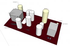
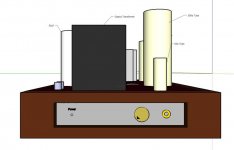
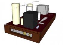
For your convenience, Kofi has attached the schematics for the circuit and the PSU along with a physical layout design from both the top and bottom perspective thanks to the fantastic Google Sketchup, six packs of Belgian beer and a modicum of child neglect.
I tried to annotate the different components-- the all-white thingees are the motor run caps, the yellow thingees are the tubes and the gray / brown thingees are the transformers.
Mostly, I need to know if the current layout is OK and maybe some ideas on the best star grounding concept. Actually, mostly what I need is some alcohol counseling, but the layout help would be good too.
Kofi
Attachments
Kofi Annan said:Mostly, I need to know if the current layout is OK and maybe some ideas on the best star grounding concept. Actually, mostly what I need is some alcohol counseling, but the layout help would be good too.
Kofi
Don't see any big issues with the layout. Star grounding should be pretty simple if you lay it out much as in the schematics. You can connect the signal ground and grid resistor together, then a small resistor (10R or so) to lift it. Then separate leads for the cathode resistor connection, the speaker return, the filament lift divider ground, and the filament center tap. I like to make a big fat buss wire for the PS grounds, then make the main star at the quietest spot on the PS ground buss. Or bring all the PS grounds together along with the others for one main star.
As for alcohol, life is short, my counsel is drink the good stuff when you can.
Sheldon
Don't see any big issues with the layout. Star grounding should be pretty simple if you lay it out much as in the schematics. You can connect the signal ground and grid resistor together, then a small resistor (10R or so) to lift it. Then separate leads for the cathode resistor connection, the speaker return, the filament lift divider ground, and the filament center tap. I like to make a big fat buss wire for the PS grounds, then make the main star at the quietest spot on the PS ground buss. Or bring all the PS grounds together along with the others for one main star.
So noted. Thanks for the advice. I'll post my version of the grounding scheme soon.
[/b]Personally, I don't like the layout. It's a matter of taste...[/b]
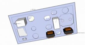
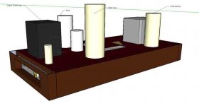
Also noted. I have revised the drawing to only have the two round caps poking through the top. I crammed the rest in there and I think I'll be able to work with this, but I'd still like some comments on the layout and positioning of components.
Have a look:
Attachments
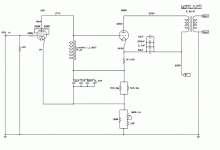
rdf said:Hello Mr. Annan. Have you run that power supply through PSUD2 yet? My immediate sense is the combination of very low first two C and very high first H will ring like a UN session closing bell.
Well, this was designed by Thorsten and completed by Luis (ligascon) to these specifications. so being a dumbass, I'm afraid to mess with it. I have actually modeled this in PSUD (well, it couldn't do the hybrid rectifier, but I did the best I could) and I thought it seemed fine. But again-- dumbass here.
Please provide your thoughts on the layout. I just want to make sure I've got adequate distances between critical components.
Kofi
Hi Kofi,
Your layout looks pretty good. Hiding the big caps under the hood may make for a cleaner look, your first cut didn’t bother me, but they take up a lot of room. If you find that you need to move a choke or something it could be a pain. Before you cut put the caps on your plate to see how much room they really take and more importantly how it will effect the wiring.
As to the circuit. I don’t like stacked bypass caps. Try just the one at first. You can always add the rest if you feel you must . If I felt that I needed to bypass I would use a single very high quality cap, maybe a .1 Teflon or something…John
2wo said:Your layout looks pretty good. Hiding the big caps under the hood may make for a cleaner look, your first cut didn’t bother me, but they take up a lot of room. If you find that you need to move a choke or something it could be a pain. Before you cut put the caps on your plate to see how much room they really take and more importantly how it will effect the wiring.
As to the circuit. I don’t like stacked bypass caps. Try just the one at first. You can always add the rest if you feel you must . If I felt that I needed to bypass I would use a single very high quality cap, maybe a .1 Teflon or something…John
Yeah-- I'll if course do a physical layout once all the parts are in. I'm drawing everything to scale in Google Sketchup, so I'm hoping I'm pretty close. That's good to know about the bypass caps. Why don't you like the stacked thingees, though?
So, I have another question...
In an effort to save expense, I'd like to get rid of the common-mode choke on the B+ supply, but I think that simply removing the component would cause problems as the rectifier would be seeing 54uF as its first capacitor, which is way too much for the 274A / B-- it should only see a maximum of 4uF in the first spot.
I'm guessing this means that I will need to add another component in between to break up the 4uF and 50uF caps; maybe a small-value resistor (1R, 5R)?
Any advice on this? Eliminating that common-mode choke would save almost $200 on the project and a little room inside the chassis as well.
Kofi
Eliminating that common-mode choke would save almost $200
I'd buy cheaper chokes (hammond maybe) and stay with a LCLC PSU.
Ciao
Gianluca
...but I'd still like some comments on the layout and positioning of components.
For esthetical reasons I would:
- move the rectifier tube away from the transformer (heat)
- switch the position of the two remaining caps (so it goes 300B- big-small)...or put the caps along the side of the amp and move the 300B in.
- move the D3A closer to the output tube (looks kinda lost alone in the corner)
- I would also try to fill in the gap in the middle of the amp (since you can't see what's underneath...
") )
)I'd like to get rid of the common-mode choke on the B+ supply, but I think that simply removing the component would cause problems...
Not only will the rectifier see too much capacitance, but you will also loose a very important component to reduce ripple on the HT...so you can't just get rid of it.
Even putting a resistor (50-100R) in place of the choke will have very different results, just simulate that in PSUD and see for yourself.
Of course nobody sez that you have to use those expensive Lundahl chokes...the psu seems to be derived from the 300B Ladyday psu that didn't use a common mode choke in that position but an unspecified "conventional" choke of 8H...
Oliver
Hmmm...
So, maybe if I replace the 20H common-mode job with a straight-up 8H choke, I'd get better ripple rejection and keep 4uF as the first cap, eh?
I modeled this is PSUD and I think this is the way to go, but I'd like some agreement on this before I order. Any agreement out there?
Also, I'll rework the layout tonight and post another photo.
Kofi
OK--- 8H choke it is.
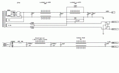
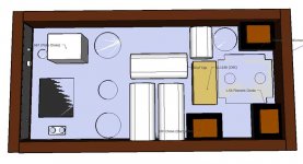
Here are some new drawings from last night. I'm thinking I may need to bite the bullet and mount some transformers on the top of the chassis, which means adding some bell-ends for appearance. I would like, however, to have it all under the hood as shown.
The issue is that there's a lot of iron in this gig and I need to be sure I won't be inducing hum in any thingees that don't need induced hum. THe bottom view of the amp goes like this now:
Left top corner to right top corner:
8H Choke (taking the place of the 20H common mode deal)
4uF Cap
274B Rectifier Tube
Plate Choke / Reactor
300b Tube
Middle left to middle right:
Power Transformer
10H Choke
2x 50uF Caps
15uF and 50uF Top-Mounted Ultrapath / Bypass Caps
d3A Tube / Output Transformer
Bottom left to bottom right:
50uF Cap
Filament Transformer for 300b
1.5A Filament Choke (with filament PSU circuit underneath)
Speaker Binding Posts
So, take a look and let me know if my layout will either destroy mankind or merely kill puppies.
Kofi
Attachments
Excellent, Mr. Annan!!
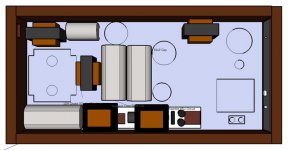
I like your layout a lot better, but to just give you a bit of a hard time I would still consider the following changes/suggestions (=nitpicking)...
- switch positions of the 4uF cap and the 274B (keep about 2" distance to the mains transformer, you'll get a nice compact capacitor pack underneath)
- you COULD (but don't have to) put the 300B on the middle axis of the amp, as well as the output trans and move the D3A just a little out. Would look nice and balanced...
- as for the hum getting into thingies where they aren't supposed to go: I am no expert, but all transformers/chokes are at 90 degrees to each other = good.
Mains transformer and output are on opposite sides = ideal
Just a little more, and you'll have a real killa...
I like your layout a lot better, but to just give you a bit of a hard time
I would still consider the following changes/suggestions (=nitpicking)...- switch positions of the 4uF cap and the 274B (keep about 2" distance to the mains transformer, you'll get a nice compact capacitor pack underneath)
- you COULD (but don't have to) put the 300B on the middle axis of the amp, as well as the output trans and move the D3A just a little out. Would look nice and balanced...
- as for the hum getting into thingies where they aren't supposed to go: I am no expert, but all transformers/chokes are at 90 degrees to each other = good.
Mains transformer and output are on opposite sides = ideal
Just a little more, and you'll have a real killa...
- Status
- This old topic is closed. If you want to reopen this topic, contact a moderator using the "Report Post" button.
- Home
- Amplifiers
- Tubes / Valves
- Kofi Annan in: "Kofi Makes a 300b DRD... and You Get to Help!"