Hello all,
I found on the web here:
http://www.diegobarone.it/
this schematic
The author says it has 8 watt of power, 10 to 50KhZ bandwith.
Has anybody tried it?
Thanks all!
I found on the web here:
http://www.diegobarone.it/
this schematic
The author says it has 8 watt of power, 10 to 50KhZ bandwith.
Has anybody tried it?
Thanks all!
Attachments
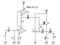
I'm sure with the right part types and values it will do as claimed or more. The only thing that strikes me as odd with that design is C3. Suppose it's some sort of bootstrapping, but it's a type I've never seen and don't know if it would work. I would think that it could be prone to oscillation. But then again I'm not the most knowledgeable guy.
Jeb-D. said:I'm sure with the right part types and values it will do as claimed or more. The only thing that strikes me as odd with that design is C3. Suppose it's some sort of bootstrapping, but it's a type I've never seen and don't know if it would work. I would think that it could be prone to oscillation. But then again I'm not the most knowledgeable guy.
That's exactly what C3 is: a bootstrapping capacitor intended to elevate the input impedance of an emitter follower. It's usually done with small signal stages, however. Not too certain just how much you can raise the input impedance of that design. It looks like it's gonna be one tough load for that SRPP.
Also, it doesn't have any sort of bias stabilization, and will probably be susceptable to thermal run-away.
I wonder if it wouldn't be a much better proposition to substitute a power MOSFET for the BJT, as a parafeed source follower.
My italian is more aproximate than my english but i think he says thay you can replace the igbt with a mosfet:
.....classe A (quindi è linearissimo sui piccoli segnali e si comporta egregiamente anche per livelli di potenza più elevati) e fa uso di un IGBT ( ) (il GT20D101 TOSHIBA, costruito espressamente per l’uso audio) ma nessuno vieta di provare anche con dei MOS (per esempio gli IRF540 sono eccellenti in questa applicazione....
the values here:
Reference Descrizione
R1 Resistenza 100k 1/4W
R2 Resistenza 390 1/4W
R3 Resistenza 470 1/4W
R4 Trimmer 470k
R5 Resistenza 10k 1/4W
C1 Condensatore poliestere 1F
C2 Condensatore poliestere 1F
C3 Condensatore elettrolitico 2.2F 25V
C4 Condensatore elettrolitico 10000F 25V
L1 Induttore 50mH 2A
T1 GT20-D101
V1 ECC88
translation service ")
.....classe A (quindi è linearissimo sui piccoli segnali e si comporta egregiamente anche per livelli di potenza più elevati) e fa uso di un IGBT ( ) (il GT20D101 TOSHIBA, costruito espressamente per l’uso audio) ma nessuno vieta di provare anche con dei MOS (per esempio gli IRF540 sono eccellenti in questa applicazione....
it means (more or less)
"is a classa A amplifier (so it is very linear on small signals and it performs very well also for higher power levels) and it use an IGBT (GT20D101 TOSHIBA, expressely designed for audio use)
but nobody forbids to try also MOSfet (for example IRF540 are excellent for this application)
The name of the project instead is a little joke beacuse HybridOne suggest ibridone, in italian a big hybrid.
Apart from that, no technical comments, sorry.
The device used is an IGBT - an insulated gate bipolar transistor, which with bootstrapping as shown should be a pretty easy load to drive. IIRC it's thermal stability is quite similar to that of a mosfet, although I cannot attest to the specific device.
I haven't the time to read the entire thread at the moment including the Italian parts (which I can read), but why not build it as specified with the specific parts recommended and see how it works?
I haven't the time to read the entire thread at the moment including the Italian parts (which I can read), but why not build it as specified with the specific parts recommended and see how it works?
kevinkr said:The device used is an IGBT - an insulated gate bipolar transistor, which with bootstrapping as shown should be a pretty easy load to drive. IIRC it's thermal stability is quite similar to that of a mosfet, although I cannot attest to the specific device.
I haven't the time to read the entire thread at the moment including the Italian parts (which I can read), but why not build it as specified with the specific parts recommended and see how it works?
I would add a DC current sensing something through the choke (adding some low ohm resistor in series with it) that adjusts voltage on the gate accordingly. For example, an integrator using one opamp, in such case it will be temperature stable, otherwise I'm afraid to load an emitter follower by low DC resistance of a choke. Also, reverse connected diode between collector and emitter would not be odd in case you forgot to connect a speaker.
Here is just the first page of the spec sheet for the GT20D101.
Input capacitance is pretty high, soa looks pretty much like a conventional bipolar. Vge of 3V gives a collector current of about 2A, 3.5V about 6A.
Some sort of bias servo probably is a good idea, but with a large heat sink and low Vce might be dispensable.
Input capacitance is pretty high, soa looks pretty much like a conventional bipolar. Vge of 3V gives a collector current of about 2A, 3.5V about 6A.
Some sort of bias servo probably is a good idea, but with a large heat sink and low Vce might be dispensable.
Attachments
kevinkr said:
Some sort of bias servo probably is a good idea, but with a large heat sink and low Vce might be dispensable.
Servo is cheaper.
Not to sure if run-away would be that much of an issue even if it were a BJT. The DCR of that choke is probably much higher than your averave emmiter resistor. There is only so much a BE junctions voltage drop can vary with heat. Also, since it is class A and not AB-B if it's is biased slightly underpowered it will give you the desired power once the opperating temp is reached. If idle current varies some it's really not that big of a deal, it is a class A.
- Status
- This old topic is closed. If you want to reopen this topic, contact a moderator using the "Report Post" button.
- Home
- Amplifiers
- Tubes / Valves
- the hybrid one