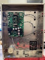
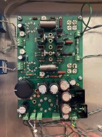
I am building a TSE-II for 300b.
I am having issues with high negative voltage at R5 / C6.
With variac at 70v AC, I read:
Negative B- Supply
R5 / C6: -450v
R6 / C7: -225v
Positive B+ Supply
R30: 141v
6.3 V winding CT
R3: 2.4v DC
My TSE-II has been installed with the parts on the inverse side. I also would like to add initially I had installed the 6.3v heated in the wrong way in T-1 Green. I had the CT connected to T1-GRN Pin 1 rather then Pin 3.
5842
pin 1: 141v
pin 3 to 9: 2.4v DC
300b
pin 2: 140v
pin 3: -21 one tube / -45 the other
pin 4: 0v
I have both C90 installed on AC 115 leads and C140 installed on HV winding center tap.
R5 is Yageo Metal Oxide Resistors 270ohm 5% 1W Metal Oxide Film RSF100JB-73-270R
C6, C7 are Kemet Aluminum Electrolytic Capacitors - Radial Leaded 450V 100uF 105C 12k Hour Radial ESU107M450AN9AA
I had for few seconds the variac at 115, the amp started to produce sound and one tube was biasing around 0.50v, while the other at less, like 0.30v or so.
At some point i started smelling burned and I turned off. R5 looks a bit blackened and C6 was very hot to the touch. C7 was much cooler.
My power supply is a UTC S-39, 490-400-0-400-490 175ma, 5v 3A, 2.5v VCT 6A, 6.3v VCT 4A.
I have it wired to the 400v HV.
What do you suggest? Replace R5 with higher wattage and C7 with higher voltage?
Do you think something is off in my circuit to have such high voltages?
Last edited:
A positive supply voltage of only 141 volts is another clue. Do you have the CT on the high voltage winding (usually red-yellow) connected to the T1 red-yel connector on the board?
A 400-0-400 volt transformer will give you nearly 500 volts of B+, far too much for most 300B's.
A 400-0-400 volt transformer will give you nearly 500 volts of B+, far too much for most 300B's.
That was it! I had connected the CT of the high voltage winding to T1-RED-2 rather then T1-RED_YEL-2!!
Now I connected it to T1-RED_YEL-2 and I managed to push up to 100v AC on the variac.
I am getting:
Negative B- Supply
R5 / C6: -438v
R6 / C7: -231v
Positive B+ Supply
R30: 294.1v
6.3 V winding CT
R3: 5.16v DC one side - 4.06v DC the other
5842
pin 1: 289.6v, turning potentiometers R9 and R20 doesn't seem to do much, maybe changing this value of 1v
pin 3 to 9: 4.06v DC
300b
pin 1: 4.8v DC
pin 2: 268v DC
pin 3: -42.3 one tube / -433.8v the other
pin 4: 0v
Both tubes are biased around 60ma
One channel sounds distorted, the other one doesn't make sound.
Any other tip on what to check next?
Thanks!

