I would be surprised if you are drawing more than 40ma for the front tubes and exceeding your 200 ma choke capacity. It would be easy enough to check the current requirements for the two driver sections by measuring voltage across R7 and calculate.
Let us know if you check - it would be useful info to have. I was planning to use a 220ma choke.
I see a drop of 23V across R7 so ~3.4mA. Do I have this right?
You are dropping average 190V across 150k, right? So, that would give about 1.3 ma through R108 and R208. Total about 2.6 ma plus some g2 current and voltage dividers. Seems about right if R7 indicates a total current of 3.4ma for the front tubes.
George, are these the operating conditions we are looking for in the driver tubes?
George, are these the operating conditions we are looking for in the driver tubes?
You are dropping average 190V across 150k, right? So, that would give about 1.3 ma through R108 and R208. Total about 2.6 ma plus some g2 current and voltage dividers. Seems about right if R7 indicates a total current of 3.4ma for the front tubes.
George, are these the operating conditions we are looking for in the driver tubes?
Sorry I had the decimal point in the wrong place, should be 2.53mA. This is using 6KT6 for the driver tube with 125V across the plate.
I was surprised by the low current passing through the driver tubes that you measured, so I looked up the datasheet for EF184/6EJ7 to find their “typical application” current is 10 ma plate and 4 ma for screen grid. See for example: https://frank.pocnet.net/sheets/030/e/EF184.pdf
Hopefully George will chime in to explain the driver tube operating conditions we should aim for. With 12GN7 George was using the difference could be more, since 12GN7 is a higher current tube.
Hopefully George will chime in to explain the driver tube operating conditions we should aim for. With 12GN7 George was using the difference could be more, since 12GN7 is a higher current tube.
This observation about its behavior under REW testing is a bit “unsettling”! Any theory about the cause of this? Has the same testing set-up produced good results on other amps you built/tested?
The computer that I used for PC based FFT testing died several years ago when the Chinesium leaked out of many of the capacitors on the motherboard. Smoke, stink, and slimy goo happened. OK, it was a nearly 15 year old PC running Win XP that had been left in an unheated storage facility during a cold winter. I made a new PC but my old WIN MLS software would not run on it. I seem to be missing a required DLL. Despite having a fully paid for license with the required software dongle, none of my email requests for upgrades, or even info on how to get it working on a Win 7 or other modern machine were ever answered by DR-Jordan Design.
This left me without PC based FFT testing for several years. I have finished rebuilding a "junkyard dog" PC with an 18 year old sound card, a 10 year old motherboard, and other "useless" parts. It is now running REW on Windows 7 and has a nearly flat loopback performance from 10 Hz to 95 KHz, so I should be back in business soon. I have to figure out REW and make some bench space before going much farther.
I did see some high frequency oscillation in my testing with the HP8903A which like the Focusrite interface and the PC based soundcard I have is a single box generator and analyzer.
My bench was a serious mess, so I cleaned up everything, but the oscillation persisted. After blowing up a few parts, I found that I had forgotten to ground one side of the OPT secondary. This makes the speaker leads antennas for transmitting high frequency energy into everything, including my unshielded input wiring (test lead wire.....not recommended). Grounding the case of the OPT helps too, and both should be done in your final build for safety reasons. This ground should be returned to the PC board, not through the chassis.
I plan on stuffing one of my boards into one of my typical "too small" chassis sometime in the near future and I will report on any unusual stuff as it happens.
Hopefully George will chime in to explain the driver tube operating conditions we should aim for. With 12GN7 George was using the difference could be more, since 12GN7 is a higher current tube.
I have tried nearly every driver tube that will fit the socket. Yes, most of them could benefit from more current, but more current without changing other parts means lower plate voltage. The plate voltage is already pretty low, and lowering it further brings some tubes into their non linear region.
Lowering the plate resistor value brings the voltage back up, but reduces the gain.
To increase the current one could simply turn up the bias current which reduces the cathode voltage. This also reduces the input headroom for the driver mosfet. To increase the headroom the control grid voltage on the tube must be increased by changing the grid voltage divider resistors.
At the point I released the schematic and BOM all of the component values were taken from the LT Spice simulation which was done with a 6EJ7 and a 6DQ5. Are they optimum for every possible tube combination? No. Are they even optimum for a 6EJ7 and a 6DQ5? Probably not, but some serious tinkering with a box full of resistors hasn't found much better yet.
I have ventured of into a side road with a CCS across the plate load resistor to increase the current without lowering the load impedance, but haven't drawn any good conclusions there either. I did see some really high power output numbers by driving the output tube right out of pure class A and using feedback to keep the THD under 3%. I'm not going further down this road until I have the FFT box set up.
I have to figure out REW and make some bench space before going much farther.
…..
Are they even optimum for a 6EJ7 and a 6DQ5? Probably not, but some serious tinkering with a box full of resistors hasn't found much better yet.
Good luck with REW; sounds like you are almost there.
Thanks for your reply re operating conditions for the 6EJ7. I take then that you expected around 1.3 ma plate current. A voltage and current chart would be helpful for us non-LTSpice-enabled beta board builders to check operating conditions of the tubes and at various point on the board.
I did some testing with REW loaded on a laptop and using it's internal sound card for input. Test signal was from a 1kHz flac file played through a Chromecast audio into both channels and 8ohm dummy loads at the outputs. Volume was set to read 2.8V at the output. I don't yet trust the overall THD measurement as it read higher than expected on both amps I tried however it gives a FFT spectrum that looks reasonable and responded to changes.
What I found is that lowering the plate voltage of the driver tubes reduced overall THD but this reduction was almost all from the 2nd harmonic. Basically the pot functioned as an H2 adjuster. Set at 125V where I have been running them so far the profile is H2 dominant as you would expect.
Current though the driver tubes was slightly higher with the 6J51P than with the 6KT6 and would also increase with lower plate voltage but these are not big changes.
What I found is that lowering the plate voltage of the driver tubes reduced overall THD but this reduction was almost all from the 2nd harmonic. Basically the pot functioned as an H2 adjuster. Set at 125V where I have been running them so far the profile is H2 dominant as you would.
Good progress with REW!
Do I understand the above quote correctly? When you say “lowering the plate voltage of the driver tube” you are not reducing the supply voltage, but instead are trimming R104 to change the bias on Q101. When you decrease the Q101 bias the V101 tube conducts more current and therefore lowering the plate voltage due to a bigger drop across the load resistor R108. Did I get this right?
Correct. All I am doing is playing with trimmer R104 and observing it's influence on the FFT spectrum....but instead are trimming R104 to change the bias on Q101. When you decrease the Q101 bias the V101 tube conducts more current and therefore lowering the plate voltage due to a bigger drop across the load resistor R108. Did I get this right?
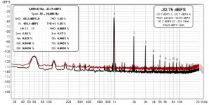
The mains noise that is shown in the REW plot is audible. I have been trying to cleanup the grounding but can still hear a buzz through the speakers. Right now I have a ground from each opt speaker outputs, one from left input to pcb, toroidal ps shield, and mains earth all meeting at one point using clip leads. Any advice on what to try next?
...OPT secondary... This ground should be returned to the PC board, not through the chassis.
I currently have the OPT secondary grounded to C9 (the two black clip leads). This has proved to be the quietest so far but doesn't seem the best place for when I put this in a chassis. Is there another recommended place to bring these grounds? The closest options seem to be the vias by the output tubes. On my SSE I connected the OPT secondaries ground to a single point with the input ground.
Attachments
Sorry you are having problems with that hum. While we wait for George’s definitive reply I would venture that it wouldn’t make much difference where on the PCB you ground the output transformer, since there should be no potential difference on the “pseudo ground plane” of the PCB. For practical reasons I plan OT/PCB ground at C2 where the copper is wider.
So what could be the problem? Have you practiced star-ground? I would look for ground loops due to multiple grounding points. I found Rod Ellliott’s piece helpful, especially figure 5 in section 9, and separating “dirty ground” from “clean or signal ground” with the ground loop breaker.
Earthing (Grounding) Your Hi-Fi - Tricks and Techniques
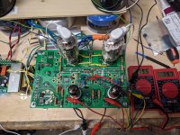
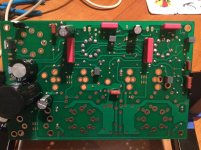
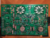
My building has been progressing slowly with soldering most the PCB parts, but I will be away on a three week vacation starting this weekend, so I hope to fire imy UNSET up somewhere in early December.
So what could be the problem? Have you practiced star-ground? I would look for ground loops due to multiple grounding points. I found Rod Ellliott’s piece helpful, especially figure 5 in section 9, and separating “dirty ground” from “clean or signal ground” with the ground loop breaker.
Earthing (Grounding) Your Hi-Fi - Tricks and Techniques
My building has been progressing slowly with soldering most the PCB parts, but I will be away on a three week vacation starting this weekend, so I hope to fire imy UNSET up somewhere in early December.
I give my experience based on instrument amps: I ground the secondary to the main supply cap (close to the rectifier) and this is the quietest point.
Concerning this specific amp, I still don't know because I've not yet completed it.
I would like to use one amp with 500V B+, 6E5P on preamp, KT88 on poweramp with 1k5 Toroidy OT used as 3k. Screens connected to 40% UL. 6E5P loaded with resistor or CCS. The second amp with GU50 in pentode mode.
Concerning this specific amp, I still don't know because I've not yet completed it.
I would like to use one amp with 500V B+, 6E5P on preamp, KT88 on poweramp with 1k5 Toroidy OT used as 3k. Screens connected to 40% UL. 6E5P loaded with resistor or CCS. The second amp with GU50 in pentode mode.
I would venture that it wouldn’t make much difference where on the PCB you ground the output transformer, since there should be no potential difference on the “pseudo ground plane” of the PCB. For practical reasons I plan OT/PCB ground at C2 where the copper is wider.
For hum purposes connecting something that draws ZERO AC or DC current should not make much difference where it connects to the board. For the purpose of killing the potential for high frequency oscillation, it does often matter since lots of gain and even small inductances and stray capacitances can cause oscillation.
If you look carefully at the PC board there are three separate “pseudo ground planes” and they meet at the star ground point, the negative terminal of C2. The output tubes, the driver tubes, and the power supply all have separate grounds, meeting at C2. All off board ground connections except for the inputs should go to the T1-RED-YEL terminal as this is the star ground point for the whole amp. The ground vias near the output tubes are probably OK for the OPT grounds if the output jacks are isolated from the chassis.
There should be exactly one connection from the chassis itself (and the transformer cases) to the PC board. Experts are divided on where this should occur. Some say it should be at C2, and I would tend to agree with this.
Others say it should be where the input jacks pass through the chassis. I have done this on some of my amps with good results, but only because the little RCA jacks that I use are hard to isolate. With nearby sweep tubes hitting large current peaks, and capable of high power oscillation at tens of MHz, I would tend to avoid trying this here.
I have not yet tried to stuff an UNSET board into a chassis, and my FFT box is not operational on the bench yet. A major bench clean up is needed to make space.
The residual hum, noise, and crud on my speaker jacks is in the 2 mV range with a similarly connected board. My black clip leads are connected to the ground end of R1, which is the power supply ground, out of convenience. C9 is actually the far end of the driver ground. This should be about the worst place to connect the OPT ground from a stability standpoint.
Next time I fire my board up, I'll play with the OPT ground point and see if it makes any difference.
The mains noise that is shown in the REW plot is audible. I have been trying to cleanup the grounding but can still hear a buzz through the speakers..... Any advice on what to try next?
Your spectral plot shows considerable 60 Hz with lots of harmonics. This would indicate that the hum could be originating in the power supply.
Some more info could be obtained by performing a few simple tests.
Fire up the board so that you can get the same plot.
Disconnect the input wiring from the board. Obviously there will be no 1 KHz tone, but do the 60 Hz and it's harmonics remain present, and at the same level.
If so, power down, remove the driver tubes and repeat the test. If the hum remains with only the output section alive, then there must be some ripple on the supply, or other means of hum coupling.
For the last few weeks I have been using the bench supply so that I can play "dial a volt" with several different tubes. I need to hook the transformer back up and make some tests.
I would like to report my progress after orders arrived. Would like some feedback if any, and I present it for the information of present and future builders.
Photos are of my build as of this afternoon. Most resistors and capacitors on the PCB are soldered now. Next I have to do the semis/heatsinks and wiring. I am planning to use 6EJ7 and 6DQ5 tubes, with about 425 Vdc at the B+ supply, employing Toroidy output transformers (TTG-KT88SE ) with Za-a of 3k ohms.
Photos are of my build as of this afternoon. Most resistors and capacitors on the PCB are soldered now. Next I have to do the semis/heatsinks and wiring. I am planning to use 6EJ7 and 6DQ5 tubes, with about 425 Vdc at the B+ supply, employing Toroidy output transformers (TTG-KT88SE ) with Za-a of 3k ohms.
Attachments
Last edited:
George, my feedback for future UNSET boards, based on my initial experience with the Beta boards:
1. For this (and future) UNSET boards, I expect very few tube rectifiers will be used (versus SS rectifiers) due to the high currents required by the TV sweep tubes, especially at higher power than your “common 300B SE amp”, the rai·son d'ê·tre for the UNSET. Why have an on-board tube rectifier? I’m using 1200 V SIC (STPSC2H12D STMicroelectronics | Mouser) rectifiers and I plan to report on how that goes. But the question is, why have the rectifier socket on board if it is not used?
2. This PCB has the power tube sockets built in (I think the original reason for this with Tubelabs was ease of supporting various levels of builders), but it still requires the builder to select, and mix and match all the inputs to the power tubes. Why have the power tubes on board if it would allow much more flexibility when off-board, and about the same “confusion factor”?
3. Same for input tubes.
After completing the Beta boards I will have more feedback. Especially on the “notes for building the UNSET beta board”.
Ciao Francois,
IIRC those points were democratically chosen in the previous thread by a number of users.
I agree that I don't like the tuberecto onboard, but others asked for it. Octal and noval onboard are quite handy IMO.
I have a question concerning the Toroidy OPTs:
TTG-KT88SE - Tube output UL transformer [3kOhm] KT88 / 300B SE - Shop Toroidy.pl
TTG-KT88PSE - Tube output UL transformer [1,5kOhm] KT88 / 300B PSE - Shop Toroidy.pl
The core of both seems the same (same size and weight), but primary and secondary winding seem different (65 vs 110 Ohm), price is the same (10 € difference).
Will it be better to use the PSE version, connecting the 8 Ohm speaker to the 4 Ohm tap?
- Home
- More Vendors...
- Tubelab
- UNSET Beta Board Build