Those do not look like the right pots either. The Bourns 3309P pots that I have been using for 10 years went extinct recently. I have been using some Piher 10 mm pots that fit fine. I'm digging through the pile of part on my bench for the empty bag to get the number. I'll post it as soon as I can find it.
I found the empty bag. The MFG's part number is PTC10LV10-104A2020 but Mouser and Digikey are out of stock. I'm looking for alternatives.
I found the empty bag. The MFG's part number is PTC10LV10-104A2020 but Mouser and Digikey are out of stock. I'm looking for alternatives.
Last edited:
Thanks, George! I see now that the trimmer I mentioned in post #60 seems to be a “finger adjust”.
The item you mentioned above is currently out of stock at Mouser, but they expect plenty to arrive by 9/24/21.
PTC10LV10-104A2020 Amphenol Piher | Mouser
The item you mentioned above is currently out of stock at Mouser, but they expect plenty to arrive by 9/24/21.
PTC10LV10-104A2020 Amphenol Piher | Mouser
Last edited:
The Digikey part mentioned by Spiggs is rated for 150 mW (the PT series). With the resistor values stated in the parts list it runs at about 100 mW, so I chose the PTC series which is rated for 330 mW. Mouser has some PT series parts in stock too, the PT10LV10-104A2020-PM-S.
Users including myself have found that setting the bias to an exact current with a single turn pot is hard to do. I chose the resistor values for R9 and R111/R211 to provide a pretty wide adjustment range so that a wide variety of tubes and supply voltages can be used with this board. These values can be increased to narrow down this range once tube selection is made, making adjustment easier and reducing power dissipation in the pot.
Users including myself have found that setting the bias to an exact current with a single turn pot is hard to do. I chose the resistor values for R9 and R111/R211 to provide a pretty wide adjustment range so that a wide variety of tubes and supply voltages can be used with this board. These values can be increased to narrow down this range once tube selection is made, making adjustment easier and reducing power dissipation in the pot.
Did some measurements using a better multi meter with fresh batteries plus a bias increase. Here is where it landed tonight.
B+ 477V
R115/R215 450V
cathode 70V
bias at 65mA
So that puts 380V across the tube and 24.7watts dissipation
Probably won't have time for the next few days to swap the speakers between the 4 and 8 ohm taps and take a good listen but that should be fun.
Interestingly I was looking at the thread "Those Magnificent Television Tubes" and saw mention of the "winglet" Sylvania 6DQ5 style tube being good for a bit more than most. I have a pair of these in the UNSET currently. Perhaps I could bump the bias up a bit more and see how it goes.
I have heard Smoking-Amp talk of such tubes on these forums for a while. The pictures of your board was the first time that I have seen one. That reminded me of a big box of used sweep tubes that I have been collecting, so I did some digging and found one. I'll test it the next time I have the opportunity to rewire my board for the 6DQ5 type tubes.
One of the most common questions I get about my amps, other peoples amps, and tube amps in general is "how many watts" or "how much power can I get?"
The answer is always a guess that requires more information than is usually provided. There is usually one sweet spot for a given tube (limited by plate dissipation in an SE amp), the supply voltage, and the OPT.
I set up my UnSET board with a Toroidy 1500 ohm OPT which can be run at 1500 or 3000 ohms. I made a chart of real measured data for both impedances. I used a 26HU5 because I have a few, and it can be used up to 50 watts for short periods of time.
For a given tube choose the maximum plate dissipation you want to run it at, and only choose combinations below that number in the "Plate diss" column. From there pick a supply voltage you can make to arrive at the best OPT load impedance, or pick an OPT and look for a convenient OPT.
You will see that the maximum efficiency coincides with symmetrical clipping. You want to be close to this point if possible.
From these charts I can see that I can get about 25 watts from the 1500 ohm OPT on 450 volts if I beat the tube hard at just over 41 watts.
Getting 25 watts with a 3000 ohm OPT needs between 42 and 46 watts on 550 volts.
It looks like my best choice is 1500 ohms, probably somewhere between 400 and 450 volts and somewhere between 100 and 110 mA.
Maybe I can push a bit more dissipation into the mosfet. Note that raising the screen voltage shifts more dissipation to the fet since more negative bias is needed.
Attachments
Last edited:
Wow, thats close to 50% efficiency 
In the charts, a total Diss of 24w is ~ 300 and 350v B+ (symmetrical clipping). Would this apply for the smaller tubes like EL34. Tubes in group 2 & 3 are pretty hard to get here but I have some vintage Mullards and Telefunken El34s.
Would those be ok? Shows around 45% efficiency and 11 - 13w.
In the charts, a total Diss of 24w is ~ 300 and 350v B+ (symmetrical clipping). Would this apply for the smaller tubes like EL34. Tubes in group 2 & 3 are pretty hard to get here but I have some vintage Mullards and Telefunken El34s.
Would those be ok? Shows around 45% efficiency and 11 - 13w.
I added the Edcor 5000 ohm OPT data to post #67.
Yes, some of the efficiency numbers are beyond the theoretical 50% maximum for a conventionally configured single ended output stage. There are two reasons for this. Measurement error, and the fact that this is NOT a conventionally configured SE stage.
I set an arbitrary 5% THD point for all measurements. This is usually the point where clipping becomes obvious on the scope, and where things start to sound "turn it down" kind of bad. All my dissipation measurements rely on low budget meters, and a 50 year old Fluke 407D power supply that is completely original. It does drift a little over time and with line voltage fluctuations. Overall I would say that the total measurement error is considerably less than 5% of reading, so the calculated efficiency is correct to within 1 or 2%.
The CED circuit drives the cathode while holding the screen grid constant and grounded for the audio signal, and also keeping the control grid relatively constant while also applying direct NFB from the plate.
Audio power is applied to the cathode, as in a grounded grid amp. This power flows directly to the plate, boosting the apparent efficiency.
This used to be a neat trick in the old days of ham radio when hams were restricted to a certain DC power input to the tube, rather than the maximum output power regulations of today.
The same thing happens in the CED circuit. The plate to control grid feedback makes the pentode work like a triode with it's grid grounded, and the power added to the cathode appears at the plate with the power made in the tube itself. This can result in a real over 50% efficiency number.
As Zintolo found in his simulations, changing the ratio between tube and fet can boost this to extremes in a computer sim, but real world limitations like mosfet SOA, limit things. For now I have been running 10 to 12% of my total dissipation in the fet. Further experiments are being done to find more options.
Back in the early days of the CED I did experiment with the KT88. It does not have the sensitive screen grid that the TV sweep tubes do. The EL34, 6L6GC and most other typical audio tubes are similar. They do not respond as well to screen drive that TV sweep tubes do, so I'm not so sure how they will work out in the UnSET, as I have not done much work with them. They will obviously need a screen supply with more than 190 volts, and probably a different divider ratio on the control grid. I will get to these experiments eventually.
Had some time for testing today. Bias at 65mA and speakers to the 4 ohm taps to give me a 6K load and took a listen. An improvement. I felt it added a bit more sharpness or clarity in the lower range with the same punch as before and that SE sound throughout.
After this I swapped the PT for an Antek 3T275 to try out a lower B+ Adjusted everything and ended up with the following
B+ 376V
R115/R215 344V
cathode 61V
bias at 80mA
So that puts 283V across the tube and 22.6watts dissipation. At this lower voltage the pots seem slightly less sensitive so hitting the target values was a bit easier.
Speakers back on the 8 ohm tap and cranked up some music. I would say this sounded at least as good as the prior test. At this point I think my test speakers are at the limits of their sound quality.
This seems like a good setup so far. I'll continue to listen to this over the next week. I have some multiturn pots on order and a softstart board to finish up next. I am also working on a way to get some capability to measure distortion so hopefully I can dial in the amp further.
What is the expected range of DF we can obtain? 2-4?
Indeed I think that higher feedback ratios are possible only in two ways: pentodes with smaller plate dissipation or parallel some p-mosfets to share the current (is it possible?). At the moment I'm simulating the circuit with GU50, as I have many of them (not macthed unfortunately) and seem a good candidate for the project.As Zintolo found in his simulations, changing the ratio between tube and fet can boost this to extremes in a computer sim, but real world limitations like mosfet SOA, limit things. For now I have been running 10 to 12% of my total dissipation in the fet. Further experiments are being done to find more options.
SpreadSpectrum in his thread with similar feedback on KT88 ( If UNSET and the RCA50W Had a Baby ) reported to have started with 10% then raised to 20% and then 30% as optimal, but I've not asked further details about how he dissipated the heat.Back in the early days of the CED I did experiment with the KT88. I will get to these experiments eventually.
Made some better measurements today.
Still not optimal, no THD so the output wattage is around visible clipping.
EL36 with the lab supply set at 350V and the 6k OPT's loaded with 4ohms to make it 3k.
Below 80mA the top clips first. At 90mA I got the most symmetrical clipping (14W output). 100 and higher gave bottom clipping first.
And yes, there was some redness on the plates. I didn't let them cook for a long time, but I was surprised to see how much abuse these little guys can take.
On to the bigger brother: E130L.
Lab supply maxed (395V). Very similar results as with the EL36. 14,5W at 100 mA. More current, bottom clipping.
On to 2 ohm load (1k5).
Now we're talking: 18W at 130mA, 22W at 140&150, 28W at 160&170mA. Yes, redness starts again.
Need more voltage!
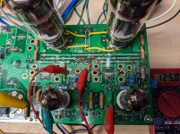
Changed out the trimmer pots for these Bourns multiturns PV37W104C01B00 and adjusted everything again. Easier now to dial in and seems to stay stable around +/- 2% of target value. Also finished up a soft start board to make turn on a little gentler.
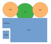
Starting to think about chassis layout. George you mentioned that oscillation can be a problem with this amp. How careful do I need to be in routing the input and output? Can I run both to the back panel keeping them as separate as possible or should I keep the inputs on the front and outputs on the rear? I am planning to mount the PT under the top plate and OPTs on top.
Starting to think about chassis layout. George you mentioned that oscillation can be a problem with this amp. How careful do I need to be in routing the input and output? Can I run both to the back panel keeping them as separate as possible or should I keep the inputs on the front and outputs on the rear? I am planning to mount the PT under the top plate and OPTs on top.
Attachments
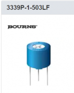
I used these trimmer resistors recently. They are a bit more pricey, but I like the idea I can mount them behind a hole drilled on the top plate.
Bourns trimmer
Bourns trimmer
Attachments
Changed out the trimmer pots for these Bourns multiturns PV37W104C01B00 and adjusted everything again.
Hi spiggs,
I found your photos of your build quite helpful. Thank you.
Also followed your lead with the multiturn trimmers, but I got 50k trimmer and a 30k and 20k resistors to use on the sides of the trimmers (to reduce dissipation). Do you know where (what value if available) the trimmers are set after your adjustments? (I hope the 20 and 30k resistors will hit the sweetspot).
I’m trying to decide if I should use 26LW6 or 6DQ5 outputs (I have several of both). What driver tubes are you using in your build with 6DQ5?
I used these trimmer resistors recently. They are a bit more pricey, but I like the idea I can mount them behind a hole drilled on the top plate.
Bourns trimmer
OldHector,
Seems like very nice trimmers at $6.00 each. I might use those for the future “UNSET ultimate build”. For the Beta Board I’ll use cheaper.
I used these trimmer resistors recently. They are a bit more pricey, but I like the idea I can mount them behind a hole drilled on the top plate.
Bourns trimmer
Hi spiggs,
I found your photos of your build quite helpful. Thank you.
Also followed your lead with the multiturn trimmers, but I got 50k trimmer and a 30k and 20k resistors to use on the sides of the trimmers (to reduce dissipation). Do you know where (what value if available) the trimmers are set after your adjustments? (I hope the 20 and 30k resistors will hit the sweetspot).
I’m trying to decide if I should use 26LW6 or 6DQ5 outputs (I have several of both). What driver tubes are you using in your build with 6DQ5?
The driver tubes I am using are 6J51P, the Russian equivalent to a 6EJ7.
Driver tube trimmers measure ~21K and 42K, bias trimmers ~29K and 42K on the board, hope this helps.
Driver tube trimmers measure ~21K and 42K, bias trimmers ~29K and 42K on the board, hope this helps.
spiggs,
Thanks, that helps. I will probably use a NOS Euro EF184 for my drivers (after testing with some older 6EJ7s).
Just to make sure I understand correctly, for the driver trimmers, did you measure 21K for channel 1, and 42K for channel 2, each between the wiper and the high voltage side? Or was that measurement between wiper and the trimmer terminal towards ground. Same question for the output tube bias trimmer.
It is interesting that the values are so close between the trimmers for the driver and output on each channel, but quite different from one channel to the other. What does that mean in terms of dissipation on the trimmers.
The measurements I posted are an average of the left and right channel
Driver tube average between the left and right first number from wiper to pin 3 21K, wiper to pin 1 42K.
Output tube average between left and right wiper to pin 3 29K, wiper to pin 1 42K.
In both cases the left and right channels were close to each other, within 1K.
Driver tube average between the left and right first number from wiper to pin 3 21K, wiper to pin 1 42K.
Output tube average between left and right wiper to pin 3 29K, wiper to pin 1 42K.
In both cases the left and right channels were close to each other, within 1K.
- Home
- More Vendors...
- Tubelab
- UNSET Beta Board Build