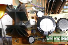
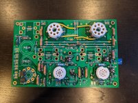
...Tubes on top (just trying some candidates here), components below deck...
What are the thoughts on the BOM heatsinks mounted below and cooling capacity? I went with the 3k Toroidy OPTs and have an Antek AS-3T350 that should put around 420-430v B+ to some 6DQ5s to try for now. With some careful placing of vent holes top and bottom am I likely to be good or should I be thinking of a more robust cooling setup?
I put together an Excel version of the BOM George posted along with another sheet that has the parts grouped by type along with the part numbers I ordered. Posting this in case it would be helpful to anyone else. Warning - I think I have made mistakes on the first pass of every BOM I have ever compiled so if you do reference it I highly recommend giving it a good once over.
Attachments
Thanks for the explanation George. There's one thing I would like to ask you: 450 V and 80 mA on 3k Ra means the current will reach zero at around 690 V, that is around 9.6 Wrms if I calculated it right. Where am I missing something?As I stated in post #11 the Toroidys that I have seem to work about as good as similar sized EI OPT's at the typical current that they would be used at for the application they are intended for.
What are the thoughts on the BOM heatsinks mounted below and cooling capacity? I went with the 3k Toroidy OPTs and have an Antek AS-3T350 that should put around 420-430v B+ to some 6DQ5s to try for now. With some careful placing of vent holes top and bottom am I likely to be good or should I be thinking of a more robust cooling setup?
Looking back through the 'UNSET is coming' thread I see George made some measurements (65C) of the heat sinks on a 15WPC build along with some thoughts.
UNSET is coming?
So if I want to build a 15 WPC capable UNSET with heat sinks on the bottom it appears some extra consideration should be given to thermal management.
There are some nice big ventilation holes in the board aligned to the radiator fins to aid airflow.
Top and bottom plate would need them too.
But quite possibly, the conclusion could be that for a setup producing more than xx Watts you'd need forced airflow for a below deck implementation.
With the FETs on the opposite side of the tubes, you could go for even bigger heatsinks.
Top and bottom plate would need them too.
But quite possibly, the conclusion could be that for a setup producing more than xx Watts you'd need forced airflow for a below deck implementation.
With the FETs on the opposite side of the tubes, you could go for even bigger heatsinks.
Last edited:
Another trick I learned some time ago....If you are building the typical metal top plate on a wood box, you can cut a rabbet in the wood where the top plate sits such that the top plate has an air gap all the way around it except at the 4 corners where it sits on the wood. I know that my explanation leaves a lot to the imagination, but this can be done with only a table saw. One can also make the hole in the top plate for the tube sockets a bit oversized allowing for some airflow there too.
This lets air out of the box. I cut a hole in the bottom plate about the same size as the PC board and put rubber feet on the 4 corners to let air into the box. Wire mesh or screen can be used to cover the hole if desired.
At this time I have not stuffed an UNSET into a box, so I can't say what's too hot. My board is sitting on the workbench with minimal airflow and the heat sinks get quite hot at power levels much above 15 watts. 30+ watts on 600 volts makes them real hot unless I point a fan at them. Some of that is heat radiation from the tubes.
I made the BOM in Excel. The forum does not accept .XLS, so I'll zip it and stick it in post #1.
Last edited:
I have an experiment I've been liking too much to take the time to do a proper build. It's over a year now. Early on, I upped the power on the driver way past what it was built for, overheating the plateload CCS .
Not wanting to do another, I just plugged a second heatsink into the top of the first one (same Avid sinks as the UNSET board), and banged them tight together. It works well !
It might be a lot better if it were one piece but it's cool enough that you can hold a finger on it for a few seconds now, which wasn't the case before.
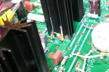
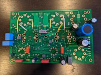
The first components are in place.
And of course the one resistor value I don't have is needed now
Oh well.
Tubes on top (just trying some candidates here), components below deck.
George,
C9 is an electrolytic on the board/schematic, but the BoM lists a 100n foil cap.
What value should we put in there?

Nice going.
On the build notes under suggested modifications it mentions a 2A pico fuse in series with the cathodes. Is this an example of the type of fuse suggested?
263 Series - PICO Fuses Axial Radial Thru hole Fuses from Fuses - Littelfuse
263 Series - PICO Fuses Axial Radial Thru hole Fuses from Fuses - Littelfuse
The 263's that you linked should work, but I have not actually tried them.
These from the 251 series are what's currently in my board.
Blocked
I also used these 1.5 amp fuses that are surplus. I got a bunch when they were on sale, but have misplaced the bag somewhere, so I bought the Digikey parts.
G23020 - (Pkg 5) 1.5Amp Picofuse
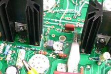
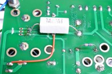
The fuse should be placed in series with the 1 ohm resistor in the cathode circuit of the output tube. It goes between the resistor and the mosfet so that one end of the resistor is still grounded. A volt meter is placed across this resistor for bias adjustment and tube current measurements.
I left a fuse lead wire pigtail sticking up for easy clip lead access. I always have a meter, scope, or both connected to this point (other lead on ground) for watching the output tube current. Since the resistor is 1 ohm the meter reads milliamps directly on the millivolt scale. The 0 to 200 mV reads 0 to 200 mA. The 2 volt range reads 0 to 2 amps.
Note the Zener diodes must be installed opposite what the silkscreen shows. This is also shown in the middle picture.
These from the 251 series are what's currently in my board.
Blocked
I also used these 1.5 amp fuses that are surplus. I got a bunch when they were on sale, but have misplaced the bag somewhere, so I bought the Digikey parts.
G23020 - (Pkg 5) 1.5Amp Picofuse
The fuse should be placed in series with the 1 ohm resistor in the cathode circuit of the output tube. It goes between the resistor and the mosfet so that one end of the resistor is still grounded. A volt meter is placed across this resistor for bias adjustment and tube current measurements.
I left a fuse lead wire pigtail sticking up for easy clip lead access. I always have a meter, scope, or both connected to this point (other lead on ground) for watching the output tube current. Since the resistor is 1 ohm the meter reads milliamps directly on the millivolt scale. The 0 to 200 mV reads 0 to 200 mA. The 2 volt range reads 0 to 2 amps.
Note the Zener diodes must be installed opposite what the silkscreen shows. This is also shown in the middle picture.
Attachments
Last edited:
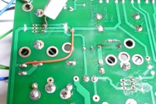
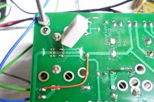
There are two ways to do this.
One involves cutting a trace in two places and adding a jumper wire and the resistor to the board.
The other involves bending the middle pin on the mosfet up and soldering the resistor directly to the mosfet pin. The other end of the resistor gets soldered to the B+ end of R4. No board mods are needed. I'll get better pics of this when I build another board.
Notice that I have used a 1.3K and a 1.5 K resistor. These work too, but 2 K may be safer if you are not trying to squeeze 30+ WPC out of the board.
Attachments
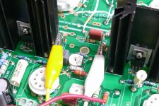
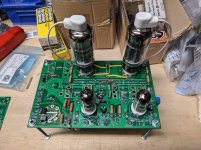
Coming together, still waiting for a few parts but all the caps are on and only R117, R217 and the 2K one on the mosfet remain for the resistors. Didn't catch the spacing requirement for C9 so that is a bit of a kludge. Anything else look amiss?
Attachments
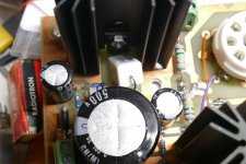
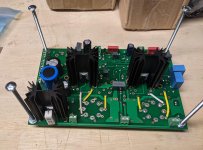
Last few parts came in and I finished stuffing the board. Put some tubes in it to see that everything fit. Next will be hooking up the power, choke, OTs then checkout. Any guidance on checkout? Can I generally refer to the TSE guide?
Attachments
Any guidance on checkout? Can I generally refer to the TSE guide?
I usually follow a method similar to the TSE / TSE-II, with a bit more caution.
All of the signals in this board are in phase. Oscillation is more likely with this setup than in a typical two stage amp like the TSE-II. The board inputs and outputs are in phase as in a three stage SE amp. Inputs and outputs should not run next to each other. A messy bench like mine was what caused several
blown mosfets. After a year of working perfectly, things started blowing up after taking the UNSET off my bench, then returning it. It turned out that I had forgotten to ground one side of my OPT secondary and the input device (a phone) was sitting on the speaker cabinet used for testing.
In order to accommodate a wide variety of output and driver tubes the bias pots have a pretty wide range. Even a small TV sweep tube can draw well over an amp of cathode current for a while, and many are rated for nearly 1.5 Amp peaks.
Start with the driver tube pots at mid range, and the output tube pots full counterclockwise when viewed from the tube socket side. Put a voltmeter across R117 and R217. With the recommended 1 ohm resistors in place, millivolts correspond to milliamps, so 80 mV across the resistors equals 80 mA through the output tubes.
With the driver tubes in place (no output tubes) and warmed up you should be able to to set the plate voltage to around 125 volts by turning the driver tube bias pot. The plate voltage is most easily measured at the end of the coupling cap (C103, C203) closest to the front edge of the board. This voltage will be adjusted again later for minimum distortion.
Install the output tubes. With no signal applied, power up and let them run for a few minutes without current, especially if they haven't seen power in say, 50 years. ALL bias adjustments must be made with no signal applied. You will find that you can't turn down the current if there is drive applied to the board. This is similar to the TSE-II, but far more pronounced.
SLOWLY turn the bias pot until tube current starts to flow. I usually set the current to about half where I will use it on unknown tubes and watch it for an hour or so. Check inside the plate area in a dark room for glowing screen grids or that pink / purple / bluish glow indicating gas. The "cobalt blue" glow on the glass itself is OK and often an indication of a good vacuum.
It is normal for the current to creep upward about 5% from a cold start as the mosfets get hot. Their current will increase with temperature.
I have seen some NOS tubes that just keep climbing. Some of these are just sleepy, and some are bad and will eventually runaway. Any unstable tube should be set aside for now until you get accustomed to how the board and your tubes work.
With a pair of stable tubes that have been on for a while, slowly turn the bias up to the desired level. At this point you can apply signal and test things out. You will probably need to readjust the driver stage bias for minimum THD. There is a fairly large range where there is no clipping and THD remains fairly constant over this range. Turn this pot slowly as small bias changes in the input tube cause large variations in output tube current. Oversized coupling caps may be common in some tube amps, but they are not your friend with sensitive sweep tubes that can draw amps of current.
Once you have the amp working with some stable output tubes, you can go back to the "creepers" found in the early testing if you have any. Set the bias to about half the current you are using with the known good tube, and then install a creeper. if the current is at, below, or slightly above the normal current, set it to the 50% point and watch this tube to see if it levels off. If so, and it remains stable for an hour or so with no glowing bits inside it was probably sleepy. If the current is well above what's normal despite being set to a 50% level on a good tube, or just keeps climbing the tube may be bad.
Note that tubes made by different companies may indeed have more than a 50% range in bias currents, especially if the two different brands behave similar to like types.

Check the screen grid voltage supply by probing the buss along the board near the output tubes. It should be around 180 to 190 volts.
If that is good check the voltage on zener diode D4 at the front of the board near C8. It should be about 56 volts.
Does the voltage on the cathode of the driver tube (pin 1, 3, or 9) vary when you turn the pot?
If that is good check the voltage on zener diode D4 at the front of the board near C8. It should be about 56 volts.
Does the voltage on the cathode of the driver tube (pin 1, 3, or 9) vary when you turn the pot?
Is across R1 the right place to measure B+ ? I put my meter there and am seeing 511V when I was expecting 420-430V with my Antek 3T350. This is with driver tubes in and no output tubes. I measured the output before hooking up the transformer and it was putting out around 718VAC.
- Home
- More Vendors...
- Tubelab
- UNSET Beta Board Build