Just doing my initial checkout after my power transformer arrived from Hammond yesterday. It's a 372HX - 600v CT. I have the primary hooked to the 120v taps (blue/brown). My wall voltage is about 121VAC.
Voltages with no tubes installed:
5842 filaments: 8.84VDC
300B filaments: 4.96VDC
5AR4 filament: 5.48VAC
B- @ R6: 266VDC
B+: -0.36VDC
First, the 5842 filaments look to be quite a bit too high? I realize the voltage will drop once there's a load on it, but I wouldn't expect it to drop 2.6v?
Second, when I install the 5AR4 it starts to arc internally after it heats up. Could this just be a bad tube?
The TSE and TSE-II uses DC on the 300B filaments and 5842 heaters. Both are derived from the 6.3 volt winding. The 6.3 volts AC is rectifier and filtered to produce about 6.8 to 7.5 volts DC under load.
Resistor R3 is used to drop the voltage for the 5842's to 6.3 volts. It's value may need to be adjusted once the amp is operational since the output tubes can draw anywhere from 2 amps (some 300B's and 45's) to 5 amps (2A3's), and line voltages vary from 112 to 128 volts or worse.
The output tubes are fed by a voltage regulator and are fixed at either 2.5 volts or 5.0 volts.
The 5AR4 is fed directly from the 5 volt winding.
Your DC voltage readings look normal for a board with no tubes. I am also using a Hammond 372HX transformer, but I am using 2A3's which eat 2.5 amps each. I have a 2.2 ohm resistor for R3 and I get 6.2 volts on my 5842's with the line voltage adjusted to 120 volts on a Variac. My line voltage varies from 122 to 128 volts depending on weather. You may need a higher value resistor for R3, but this can't be determined until the amp is completely finished, since all loads on the transformer will affect all of the output voltages to some extent.
The sparking in the 5AR4 is NOT normal. Yes, it could be a bad tube, but it could also be a short on the B+ line. Disconnect the choke, or remove R4 if it's present, verify that C4 is installed correctly and that then retest.
Measure the voltage across C4 while performing this test. Place the black meter probe in one of the T1-RED-YEL terminals, and the red meter probe in the CHOKE terminal closest to the 5AR4 socket
It should rise to nearly 400 volts with no load. Be aware that without a choke or R4, C4 will remain charged after this test and must be discharged manually. Or you can simply leave the meter connected and wait until it reads less than 30 volts or so. The meter itself becomes the bleeder resistor, albeit a slow one.
That transformer has two heater windings (5V 3A, 6.3V 6A), and both are centre tapped. How did you measure 3 different heater winding volatages?
I measured the heater voltages at the tube sockets. So DC for the output and driver stages, both derived from the 6.3v winding, and AC directly from the 5v winding for the rectifier.
Thank you, George. I’ll see how the heater voltage for the 5842s settles out once the amp is running, and adjust R3 as needed.
I verified C4 is installed correctly. Disconnected the choke, installed the 5AR4, and measured across C4 (red-yel and choke 01). No voltage was developed at all. The heaters on the tube came up along with some tinkling sounds, but no voltage. I assume this means the rectifier is in fact bad. When I get the new 5AR4 I’ll do the same test before reinstalling the choke.
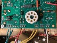
I’m attaching a shot of the left side of the board with the PT connections for reference. (Note the black wires coming into the star ground point are from the inputs. The white is from the IEC earth ground. To the left you might see the terminals of the supplemental motor run cap that’s connected in parallel with C5. The amp is currently just set up temporarily on a piece of plywood for checkout.)
Attachments
When measuring xfmr terminal voltages, all secondaries have to be loaded to conduct their rated current. If this is not done, then all the open circuit (unloaded) voltages will appear to be high.
Thank you, understood. Just wanted to get some quick perspective on the 5842 voltage since it was ~40% over target compared to the 5AR4 heater being just ~10% over target. The 5842s aren't exactly cheap. The bigger concern was the arcing 5AR4.
I got the new 5AR4 today and tried the test again. The voltage at Choke 1 without the choke installed came up to 458vdc after the rectifier warmed up, confirming the old one was bad.
I then waited over 5 mins, made sure C4 was drained, hooked up the choke, powered up again with no tubes installed. Voltage started to climb slightly as the rectifier warmed up, followed by more internal arcing in the 5AR4. I immediately shut things down again, disconnected the choke, waited another 5 mins, powered up again, and confirmed that I again have the ~460vdc across C4. So at least I haven't fried the new 5AR4 yet.
So, likely short in the B+ line then? I've checked all the components for correct orientation and haven't found anything amiss yet, but I will check again. Any suggestions about further tests to narrow down where the problem is?
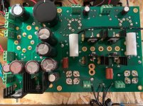
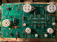
Full pics of both sides of the board attached for reference.
I then waited over 5 mins, made sure C4 was drained, hooked up the choke, powered up again with no tubes installed. Voltage started to climb slightly as the rectifier warmed up, followed by more internal arcing in the 5AR4. I immediately shut things down again, disconnected the choke, waited another 5 mins, powered up again, and confirmed that I again have the ~460vdc across C4. So at least I haven't fried the new 5AR4 yet.
So, likely short in the B+ line then? I've checked all the components for correct orientation and haven't found anything amiss yet, but I will check again. Any suggestions about further tests to narrow down where the problem is?
Full pics of both sides of the board attached for reference.
Attachments
Thanks for the encouragement George. After biasing up the output tubes my B+ dropped to 320v. I thought it wasn’t unlikely the shenanigans with the backwards diode beat the 5AR4 up too much, so before drawing any conclusions I ordered a new, tested Sovtek from a reliable source. That came today so I was able to run some more tests.
With 120v supply from the cardiac, all tubes in, drivers adjusted to 175v at the plate, outputs bias adjusted to drop .6v over the sensing resistors (60mA), I’ve got a B+ of just 340v and the 5842 heaters are at 5.6vdc.
(The OPTs are Electraprint 5k primary 65mA rated with 4 and 8 ohm taps. Measurements are into non-inductive 4ohm resistive loads on the 4ohm taps.)
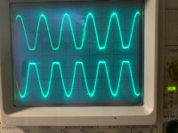
Getting about 5.8w at the onset of clipping, and the clipping is asymmetrical (see attached). It’s the driver stage that’s limiting things here, since I see the asymmetrical clipping at the 5842 plates.
I’m less worried about the B+ but would still like to account for what’s going on there too. I know you’ve said you’re also using a 372HX and are getting around 385v B+. With the 5k primaries and without the driver clipping I’d expect to get maybe another clean watt out of it at 340v, while closer to 400v the operating point charts say I can expect just maybe one more additional watt with essentially the same 2nd and 3rd harmonics. So, not a huge deal, but I don’t like leaving these things unexplained, and I could use those extra 2 watts.
Any ideas about what to look at next?
With 120v supply from the cardiac, all tubes in, drivers adjusted to 175v at the plate, outputs bias adjusted to drop .6v over the sensing resistors (60mA), I’ve got a B+ of just 340v and the 5842 heaters are at 5.6vdc.
(The OPTs are Electraprint 5k primary 65mA rated with 4 and 8 ohm taps. Measurements are into non-inductive 4ohm resistive loads on the 4ohm taps.)
Getting about 5.8w at the onset of clipping, and the clipping is asymmetrical (see attached). It’s the driver stage that’s limiting things here, since I see the asymmetrical clipping at the 5842 plates.
I’m less worried about the B+ but would still like to account for what’s going on there too. I know you’ve said you’re also using a 372HX and are getting around 385v B+. With the 5k primaries and without the driver clipping I’d expect to get maybe another clean watt out of it at 340v, while closer to 400v the operating point charts say I can expect just maybe one more additional watt with essentially the same 2nd and 3rd harmonics. So, not a huge deal, but I don’t like leaving these things unexplained, and I could use those extra 2 watts.
Any ideas about what to look at next?
Attachments
Last edited:
If it's the driver stage that's causing the clipping, first get the heater voltage as close as possible to 6.3 volts. Then try turning the adjustment pot that sets the plate voltage on the 5842. 5842's are highly variable most work best at around 175 volts, but some do better on a different voltage.
I had to wait for some resistors to keep experimenting. With a 1.2ohm resistor at R3 instead of the 2.2ohm the heaters of the 5842s are at 6.2v. I also switched to a Hammond 276X, which got my B+ up to 365v. (I also switched to a 500v 100uF WIMA DC link cap as the supplemental one across C5 instead of the huge motor run cap I had in there before.) I'm no longer seeing the early uneven clipping at the plates of the driver now, even with the driver voltages still set at 175v.
I am still seeing asymmetrical clipping at the outputs though. I'm at right about 6 watts output before that kicks in, which is pretty near what I expect for max clean power. But I wonder if the asymmetrical clipping is an indication of something that may affect pre-clipping performance as well? I'm running the 300Bs at 60mA now, but tried bumping that to 80mA and dropping it to 50mA and in neither case was there a change in the clipping characteristics.
It sounds great so far, by the way. Thank you George! Wonderful, big, airy, and very detailed even without anything broken in. Just want to check all the boxes and make sure I haven't made a mistake somewhere along the way.
Asymmetrical clipping is somewhat normal in an SE amp.
In a push pull amp you have two identical circuits, each working on part or most of the waveform. Unless something is seriously out of balance the clipping will be symmetrical.
In a Single Ended amp there is only one output device. Clipping is caused by running out of voltage headroom as the current goes to zero (cutoff), or by running out of current carrying capability through the tube - OPT pair as the tube tries to pull its plate down to the cathode (saturation).
Note that at the PLATE of the TUBE, top clipping is from running out of voltage headroom and bottom clipping is from running into tube saturation. These may be reversed at the speaker terminals depending on how the OPT is wound.
Do not connect your scope directly to the plate of the output tube without a voltage divider or HV probe. The plate voltage will swing to nearly twice the B+ voltage under normal operation, and much higher if the amp is hard clipped.
Which of these happens first is dependent on the load impedance, the power supply voltage, and the tube's characteristics which are bias current dependent.
When I'm testing a new design on my bench I use a variable bench power supply so I can find the optimum supply voltage for a given combination of circuit, tube and load. There is usually a few valid combinations of supply voltages and bias currents that will result in symmetrical clipping when testing with sine waves into a load resistor. We don't listen to sine waves or resistors, and all that optimization is lost as soon as I hook up the speakers and crank up some loud dynamic music.
Speakers are not resistors, and rarely even match their published impedance VS frequency curves, since those curves were made with single tone sine waves at a fairly low level.
It is usually possible to adjust the B+ voltage and / or tube current to make the clipping more symmetrical with music into speakers, but that is lost if different speakers are used, or the music being played has significantly different content.
Reviving this relevant thread instead of creating a new one:
I am also getting ready for a 300B TSE-II build…
For power transformer, I’m thinking this one:
edcorusa.com/products/xpwr049-570v-220ma-ct-6-3v-2-9a-5v-5a?variant=41262229160123
otherwise this one:
edcorusa.com/products/xpwr225-600v300-0-300-300ma-6-3v-5a-5v-5a?variant=41570781298875
For OPTs, I am thinking this:
https://edcorusa.com/products/cxse2...ube-output-transformer?variant=41523186860219
This amp will target speakers and headphones (with a suitable resistor network arrangement).
Do you see any problem with these choices?
- Home
- More Vendors...
- Tubelab
- TSE-II 300B Checkout Help