I have recently built a TubeLab SSE and I am in the process now of building a TSE-II, so much fun!
I have noticed that the TSE-II has two 10 ohm resistors R18 and R29 used to measure the bias voltage.
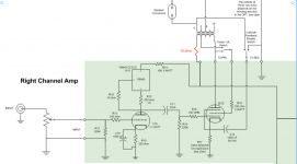
Would it be possible to install the same 10 ohm resistors to the SSE as well? If so, would they go on the other lead coming from the output transformer like the one in red in the attached picture?
Thanks!
I have noticed that the TSE-II has two 10 ohm resistors R18 and R29 used to measure the bias voltage.
Would it be possible to install the same 10 ohm resistors to the SSE as well? If so, would they go on the other lead coming from the output transformer like the one in red in the attached picture?
Thanks!
Attachments
It is what I am doing now. I have installed two test plugs on each side of R27 and R17, and one test plug for plate voltage.
Since I have connected two potentiometer changing the value of R27 and R17, to calculate the bias appropriately I have to measure the resistance of R27 and R17, depending on how much the potentiometer is turned, then the voltage drop across said resistors, then the plate voltage.
The potentiometer change the value of R27 and R17 anywhere between 300ohms and 1000ohms. I have to revise it to a resistor in parallel with the potentiometer plus another resistor as discussed in this thread SSE Cathode Bias Resistor Value swings when cathode feedback is not used
Anyway... the method works but it is a bit slow.
If I could just add a 10ohm resistor and install some sort of meter (say like a Marantz 8b), that would be faster and possibly look cool
Is there a danger that you are misunderstanding how the tube operates with cathode bias? It is designed to control the current through the tube, not the voltage. The tube conducts until the grid becomes sufficiently negative wrt the cathode, due to the voltage loss in the cathode resistor, and that set the idle point of the tube.
Using this method, as the tube ages, it will have less emission, and the operating point (grid negative voltage) can adapt to the tube. The same current flows, and the anode potential is not radically changed.
What are you measuring with the plug for the anode voltage? Isn't there a danger a very high voltage can potentially be touched by prying fingers?
In any cathode biased amp like the SSE, the preferred method is to put the sense resistor in the cathode lead at the ground end. As stated this puts one end of the meter at ground level so that even the cheap Chinese digital meters found on Amazon and elsewhere for a few bucks will work fine.
This can also be done on fixed bias amps with indirectly heated tubes, since the cathode is usually grounded.
It will not work on the TSE design since the tubes are DHT's with no separate cathode using DC heating to eliminate line frequency IMD products. In this case an individual filament regulator, rectifier, and heater winding would be required, so the plate current is sensed in the plate supply side.