Hi All,
So this is my first electronics project and I am an absolute beginner with all this stuff. I have spent the last couple months putting together George's Simple SE. tried to start my checkout today by metering between R4 and ground. When I turned the power bar on nothing happened. No voltage reading, no light, no smoke. I have two ideas of what it might be besides the fact that I have no idea what I am doing.
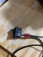
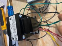
Firstly I purchased an on-on switch by accident. I may have wired this wrong. I wired the middle prong to the opt, and the bottom prong to the fused plug.
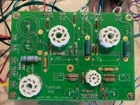
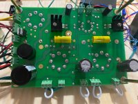
My other thought might be the empty sockets labeled D4, D3, and TR1. I saw in some other threads that these need diodes and a in-rush current limiter. Is that still the case?
Cheers,
Bassy
So this is my first electronics project and I am an absolute beginner with all this stuff. I have spent the last couple months putting together George's Simple SE. tried to start my checkout today by metering between R4 and ground. When I turned the power bar on nothing happened. No voltage reading, no light, no smoke. I have two ideas of what it might be besides the fact that I have no idea what I am doing.
Firstly I purchased an on-on switch by accident. I may have wired this wrong. I wired the middle prong to the opt, and the bottom prong to the fused plug.
My other thought might be the empty sockets labeled D4, D3, and TR1. I saw in some other threads that these need diodes and a in-rush current limiter. Is that still the case?
Cheers,
Bassy
Attachments
You're right.
You don't know what you're doing, and neither do I.
However, jumping into dangerous tasks like tube amps requires some education - from books, and learning the fundamental basics of electronics.
If you insist on skipping those mandatory lessons, good luck with that,
You don't know what you're doing, and neither do I.
However, jumping into dangerous tasks like tube amps requires some education - from books, and learning the fundamental basics of electronics.
If you insist on skipping those mandatory lessons, good luck with that,
My other thought might be the empty sockets labeled D4, D3, and TR1. I saw in some other threads that these need diodes and a in-rush current limiter. Is that still the case?
Bassy
This is still the case, yes.
Start here & populate with the 2 diodes & inrush limiter. You can use jumpers to test if you wish, but that defeats the (important) purpose of George's board change.
Wow. First project, eh? Welcome to the big leagues of B+ of 350 VDC or greater.
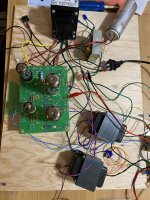
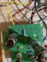
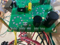
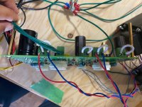
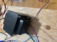
Well, unplug the whole thing if you haven't already, drain the capacitors with a resistor so you don't get any surprise shocks, remove the vaccum tubes, and take more pictures of the underside of the board, the top side minus tubes, and the wiring from the PT and OPT iron.
Next, do you have a checklist of components installed, a checklist of things to do in order, and whatever else maybe that you wrote down? Have that handy. It will be a nice reminder to say what you left out and what you added.
Some clarification. You said you powered it up the first time. Did you power up the whole thing the first time using a variac or a simple dim bulb tester? If so, what were the readings from your voltmeter when you were slowly powering it up? These things keep parts from frying because frying can be very noticeable with smoke and scorch marks or something almost invisible.
Information (as much as you have) because people don't have x-ray vision and no one else was there to see steps in assembly or the power up. The information helps because it could be one missing component or one forgotten solder joint.
Last edited:
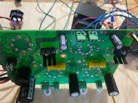
That switch with the main voltage in pictures 3 is dangerous. insulate that wires as minimum and mount the switch firmly. Also the big cap must be securely mounted.
Then check all the wiring with the schmeatics...
Remove the tubes and go slowly, steep by steep...
Good luck
Thank you for the advice. Regarding insulating the switch connections, can I just use electrical tape temporarily? Once I have tested everything I will be building an enclosure and was going solder some of the connections and use heat shrink over them.
As stated, a pair of 1N4007 or UF4007 diodes and a CL-140 current limiter are needed in the missing component holes. They can be replaced with a wire jumper for a quick test, but this places extra stress on the rectifier tube.
Did the internal heaters glow orange inside the tubes after a minute or so? If so, then the missing parts could be the only issue.
Please be careful with your setup. To not go poking around in it while it is plugged in. I make a habit of using a power strip to plug in the power cord. Turn off the power strip, then remove the power cord completely before touching anything in the amp. This makes two actions necessary to re-power the amp.
I learned the hard way that simply yanking the power cord is not good enough when all cords are black and the cord for the soldering iron looks just like the cord for the amp.
Last edited:
Wow. First project, eh? Welcome to the big leagues of B+ of 350 VDC or greater.
Well, unplug the whole thing if you haven't already, drain the capacitors with a resistor so you don't get any surprise shocks, remove the vaccum tubes, and take more pictures of the underside of the board, the top side minus tubes, and the wiring from the PT and OPT iron.
Next, do you have a checklist of components installed, a checklist of things to do in order, and whatever else maybe that you wrote down? Have that handy. It will be a nice reminder to say what you left out and what you added.
Some clarification. You said you powered it up the first time. Did you power up the whole thing the first time using a variac or a simple dim bulb tester? If so, what were the readings from your voltmeter when you were slowly powering it up? These things keep parts from frying because frying can be very noticeable with smoke and scorch marks or something almost invisible.
Information (as much as you have) because people don't have x-ray vision and no one else was there to see steps in assembly or the power up. The information helps because it could be one missing component or one forgotten solder joint.
Hi Overtheairbroadcast,
Yeah, first one. May have bitten off more than I should chew, but I'm here now.
I checked all the capacitors before I tried to drain them but they were not showing any charge on my multimeter. Everything has been unplugged and the tubes removed.
I have attached my BOM. I borrowed it from Mmcaleer, and made a few changes due to availability. As far as how i went about installing things, I essentially followed the instructions on Georges website.
When I powered it up I just put my multimeter on between R4 and star ground, had it plugged into a power strip and flipped the switch. As I did not see a voltage reading after a few seconds or smoke I powered it down.
Thanks for your feed back,
Bassy
As stated, a pair of 1N4007 or UF4007 diodes and a CL-140 current limiter are needed in the missing component holes. They can be replaced with a wire jumper for a quick test, but this places extra stress on the rectifier tube.
Did the internal heaters glow orange inside the tubes after a minute or so? If so, then the missing parts could be the only issue.
Please be careful with your setup. To not go poking around in it while it is plugged in. I make a habit of using a power strip to plug in the power cord. **** off the power strip, then remove the power cord completely before touching anything in the amp. This makes two actions necessary to re-power the amp.
I learned the hard way that simply yanking the power cord is not good enough when all cords are black and the cord for the soldering iron looks just like the cord for the amp.
Hi George,
I did follow your advice and plugged my amp into a power strip. I was well away from it when I powered it on. As stated above I had my multimeter (only one) set up between r4 and star ground. It showed no voltage so I shut it off after only a few seconds. Was this because of the missing components? I will pick up the diodes and in-rush limiter today and retest. Can I use a CL-160 or CL-90 in place of the CL-140 by chance? I have them on hand and my local shop does not carry the CL-140 so it would be a wait from mouser before trying again.
Cheers,
Bassy
Last edited:
Hi Overtheairbroadcast,
Yeah, first one. May have bitten off more than I should chew, but I'm here now.
I checked all the capacitors before I tried to drain them but they were not showing any charge on my multimeter. Everything has been unplugged and the tubes removed.
I have attached my BOM. I borrowed it from Mmcaleer, and made a few changes due to availability. As far as how i went about installing things, I essentially followed the instructions on Georges website.
When I powered it up I just put my multimeter on between R4 and star ground, had it plugged into a power strip and flipped the switch. As I did not see a voltage reading after a few seconds or smoke I powered it down.
Thanks for your feed back,
Bassy
Forgot the pictures and BOM
Attachments
- Status
- This old topic is closed. If you want to reopen this topic, contact a moderator using the "Report Post" button.
- Home
- More Vendors...
- Tubelab
- No Power to SSE amp on first power up attempt