After lurking, reading, and finally purchasing a board, I’m ready to jump off the cliff. I’ve built everything from Porsche engines to acoustic guitars, so my own tube amp is next. I’ve done some minor audio projects (recaps, etc.) and am fair with a soldering iron. I’ll be posting tons, and asking for feedback as I go. Thanks in advance for all the help I’ll get! —Jaybird
Attachments
After lurking, reading, and finally purchasing a board, I’m ready to jump off the cliff. I’ve built everything from Porsche engines to acoustic guitars, so my own tube amp is next. I’ve done some minor audio projects (recaps, etc.) and am fair with a soldering iron. I’ll be posting tons, and asking for feedback as I go. Thanks in advance for all the help I’ll get! —Jaybird
Fasten seat belts ! 300b's with the TSE-II is an incredible amplifier. It made me wonder what the fuss was with commercial units, when, with a little effort this is possible.
Don't forget to check the parachute beforehand...I’m ready to jump off the cliff.

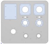
what kind of enclosure are you planning on using? kinda changes where you place parts on the board (top vs bottom)
I'm planning on a bottom-o-the-bard build as I want those tubes up in the air! I am still considering top plate configurations, and will post a few of my FPE designs for feedback. One thing I am seriously considering is mounting the 45 tube sockets off the printed board. From what I've read, mounting the WE417 tubes off the board is a bad idea. --Jaybird
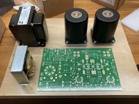
Very cool! Where did you buy the output transformers from?
I scrambled the James transformers off Fleabay. I have read great reviews on them, and found a good deal on this pair. They started off as the foundation of the build. My original plan was to build Gordon Rankin's "Bugle" 45-based amp with point-to-point wiring. I discovered that the TSE-II was out, and that clinched it for me--seemed like the simplest way to get my first amp built. --jaybird
The instructions for the SSE clearly show caps/mosfets on bottom and resistors on the top. I dont think there is any such guide for the TSE or TSEII. I can tell you it works just fine except put large resistors under the board also. I use 1/2" standoffs to mount board to underside of top plate and clearance is no problem. The 9 and 8 pin sockets are basically flush with top and 4 pin sockets stand about 1/4" proud.
Some pictures of my layout and board underside here
Tubelab SEII Chassis
Some pictures of my layout and board underside here
Tubelab SEII Chassis
I have the orig TSE with james 6123 outputs and it's a great amp. The Straightforward way to populate the board is to put the tube sockets on top, then everything else on the bottom. The resistors obviously don't have any polarity concerns, nor do the film caps. The electrolytics have polarity to get right (easy 50/50 chance!! haha), and the mosfets and filament voltage regulator have 3 (or more) legs to get right....usually you just spin them 180 deg when installing them on the bottom...but you need to triple check them...depends on where the gate/source drain pinouts are. CONVINCE yourself that the mosfets and filament regulator are wired correctly before firing it up.....
With the sockets soldered directly to the board, I "hung" the board from the chassis top plate with short standoffs.....that resulted in the sockets being more or less flush with the top of the top plate.
Other advice: If you haven't yet..buy clip leads for your multimeter(s)....that way you can bring the amp up and test voltages hands free. Clip the leads where you want to measure then power up the amp. These can be a lifesaver.
Last edited:
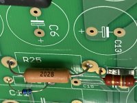
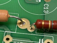
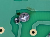
Thanks boywonder! Good advice. Phase 1 is complete, and all the resistors are soldered in place. Any thoughts or concerns?? The only real concern I had is that the pads of R25 and R33 are very close together (looks like they touch). On the back of the board, the solder bridged from one leg of 25 to 33. I used a solder wick to clean as much as I could... do you think it will be OK? Onward through the fog....
Attachments
Last edited:
Thanks boywonder! Good advice. Phase 1 is complete, and all the resistors are soldered in place. Any thoughts or concerns?? The only real concern I had is that the pads of R25 and R33 are very close together (looks like they touch). On the back of the board, the solder bridged from one leg of 25 to 33. I used a solder wick to clean as much as I could... do you think it will be OK? Onward through the fog....
Looking good Jaybird. I put the trimmers on the bottom - the choices are to have it on top which is fine when the board is not in a chassis, or underneath the PCB, where access is easier after you've mounted the board.
Any ideas around mounting D1 ? I bent the pins and mounted it horizontal. Pic here. Please ignore the regulator in the pic. It is the wrong type and George picked up the mistake.
Last edited:
All,
I remember seeing a construction guide with instructions for bottom-mounting all of the components but resistors and sockets. I've been back over the Tubelab site and construction pages, but can't seem to find it. Can someone point me toward it? Thanks!--Jaybird
Im pretty sure those notes are burried in the tse is dead thread. I build my amp the same way and have to reference it a few times. If you have issues finding it let me know and I can snap a few pictures of the understand of my amp for you.
Here are a couple pics of my Orig TSE:
https://www.diyaudio.com/forums/tubelab/157491-pictures-tubelab-amp-3.html#post2476436
Post #126 is the topside and post #133 is the bottom side. The board is suspended off the the underside of the top panel with 4 short standoffs. You can see the screw heads holding the standoffs to the top panel in the top view. Standoffs are female-female thread. The most difficult thing is to get all the holes in the top panel in the right place.
You could make the tube socket holes in the top panel oversized; that would allow for some ventilation and some wiggle-room for concentricity issues as well....I milled slots behind the 300B's for ventilation.
It looks like I got fancy and used one of the board's mounting screws to also hold the choke...haha.....to minimize hardware showing on the top panel.
I did the same technique on another TSE build using 45 tubes....post #226 here:
https://www.diyaudio.com/forums/tubelab/157491-pictures-tubelab-amp-5.html#post3361885
Last edited:
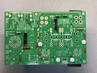
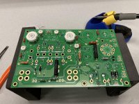
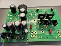
Progress!! I have the board populated for the most part. Pics are attached. I still need to mount the coupling caps, but need to figure out the best way to mount them to the board. Also, I have not mounted the rectifier or power tube sockets as I’m still toying with off-board mounting. This was my first board build—kinda surprised how quickly it went.
Attachments
R6 and R36 will be Hot
Hello, R6 and R36 will be hot and may be a good idea to provide them with more air / more open space when it is in operation (solder it at the bottom of PCB)
Progress!! I have the board populated for the most part. Pics are attached. I still need to mount the coupling caps, but need to figure out the best way to mount them to the board. Also, I have not mounted the rectifier or power tube sockets as I’m still toying with off-board mounting. This was my first board build—kinda surprised how quickly it went.
Hello, R6 and R36 will be hot and may be a good idea to provide them with more air / more open space when it is in operation (solder it at the bottom of PCB)
- Home
- More Vendors...
- Tubelab
- Jaybird’s TSE-II build...here we go!