I was wondering whether it would be possible to include an Arduino in my SSE build, ...
I wonder whether the stats might detract from the enjoyment of the amp? I checked voltages in my Quads, and they were all over the shop, but no particular limit was being exceeded, and the amps always sound excellent. Tubes are not like exact mechanical parts.
Everything's ordered and I'll start building as soon as I receive the components.
I was wondering whether it would be possible to include an Arduino in my SSE build, hooked to a screen monitoring watt per channel, time since I turned on the amp, temperature, etc.
I looked through the forum but can't seem to find anyone who's done it before.
Go for it! That's why it's called DIY Audio. Write some code, collect the data, chart and graph away.
Let everybody on the forum know what and how you did it.
A MS degree student friend of my son's saw my live steam locomotive and old car without fuel injection and said that they represent old technology without any computer software/hardware.
My reply is that is why I like them.
I was wondering whether it would be possible to include an Arduino in my SSE build
I did it with a TSEII last year. It operates a remote volume control.
Attachments
Finally received my board after a month (and belgian customs keeping the package for ten days before asking me to shell out the price of my order as 'import and treatment fees')
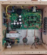
Here it is, already populated, only missing a few parts, semi-conductors and terminals.
If somewhat was kind enough to check if I did a good enough job soldering? I used Mundorf Supreme 10% silver solder heated to 290°C. There was some flux splatter, but apart from that, every joint seems good and sturdy.
Great to see your progress!
I'm not qualified to critique your soldering job.
The only comment I will make is that I think your cathode bias resistors should be on the opposite side of the board, if you plan on mounting the board under the chassis top plate. Not just for clearance, but also for cooling.
I'm not qualified to critique your soldering job.
The only comment I will make is that I think your cathode bias resistors should be on the opposite side of the board, if you plan on mounting the board under the chassis top plate. Not just for clearance, but also for cooling.
- Status
- This old topic is closed. If you want to reopen this topic, contact a moderator using the "Report Post" button.