I've populated the board, built the chassis, now all thats left to do is wire it up! Posting some pictures of progress, and would love some constructive criticism. Any idea of the best place for my choke and capacitor? Will volume pot be ok by the power side?
I find this forum to be so incredibly valuable. Love the pictures, and parts lists, that have been posted. Most of my questions have been answered by reading and re reading posts. Hope this helps someone as well.
I find this forum to be so incredibly valuable. Love the pictures, and parts lists, that have been posted. Most of my questions have been answered by reading and re reading posts. Hope this helps someone as well.


Looking great so far.
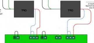
If there is a way to fit both the choke and the cap over on the "power" side of the chassis, that would be best. The proposed layout (last photo) brings high voltage all the way over to where all the OPT wiring (and the input wiring) will be, which is not ideal at all. Whether it will cause audible issues or not, I cannot say - but it is generally discouraged by the experts.
If there is a way to fit both the choke and the cap over on the "power" side of the chassis, that would be best. The proposed layout (last photo) brings high voltage all the way over to where all the OPT wiring (and the input wiring) will be, which is not ideal at all. Whether it will cause audible issues or not, I cannot say - but it is generally discouraged by the experts.
I highly recommend taking George's advice (as written on his wiring diagrams page) - wire it up as a simple triode with no CFB first and test it out. The wiring for that is really straightforward, and if you like the sound you might decide to stop there. It seems like the vast majority of people use their SSE this way.
Go through George's instructions a few times, then attack one thing at a time. If you are unsure about something, just ask. Oddly, despite my lack of knowledge and experience, I found the basic wiring very easy so I will help if you need it. I am sure others will too.
It really does start to become a brain twister if/when you start trying to wire up switches for UL/triode and CFB. Get all the rest right first.
Once you get it to the point where you are ready to flip the switch, post a photo and we can have a quick look. A 2nd, 3rd or 4th pair of eyes is never a bad thing.
Since you've done a 2-sided board, like I did - One thing that I found very helpful was to flip the board template/image and use it as a guide.
Tubelab Simple SE Reverse Board Template
Tubelab Simple SE Reverse Board Template

Outputs transformers
Yellow speaker positive
White speaker negative
Blue T-2 position 3, with jump wire attached to pos 2
Red to T-2 position 1
White Blue not used.
Sorry for all the questions, I'm colorblind. Will be having my son help with colors, just need to know I have a solid plan in place.

Yellow speaker positive
White speaker negative
Blue T-2 position 3, with jump wire attached to pos 2
Red to T-2 position 1
White Blue not used.
Sorry for all the questions, I'm colorblind. Will be having my son help with colors, just need to know I have a solid plan in place.
This is a lot more confusing than I thought!
Included picture of Edcor label.
Let's make sure I've got this correct.
Yellow wire to T1 green
Black red wire to T1 red-yellow
Red to T1 red
Brown to T1 yellow
White Brown wire not used, capped off.
Sorry for the delayed response.
No sir. Your yellow wires are the 5V winding so they should be going to the T1-YEL terminals as per the first diagram (and paragraph below it) here Wiring Diagrams | Tubelab
The two browns (6.3V) will go to T1-GRN.
The rest is correct.
Last edited:
Outputs transformers
Yellow speaker positive
White speaker negative
Blue T-2 position 3, with jump wire attached to pos 2
Red to T-2 position 1
White Blue not used.
Sorry for all the questions, I'm colorblind. Will be having my son help with colors, just need to know I have a solid plan in place.
Yellow and white, correct.
See attached, a flipped version of George's standard triode connected diagram (because your terminals are on the bottom of the board). Hopefully this will remove all doubt about which terminals to connect the red and blue wires & jumper.
Attachments
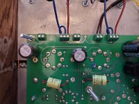
1st image, lower-left next to the big cap looks like a cold joint in the making? Personally, I would probably try to cover the pads with solder, maybe even on both sides, just to ensure everything is well-connected.
In following the various build threads here, one of the most common problems for first-time builders is a cold joint somewhere causing various amounts of smoke, noise, and hum, and no shortage of deflated excitement for first power-up!
Also, maybe a q-tip to remove the excess heat compound. That stuff gets everywhere if you're not careful!
Last edited:
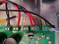
Progress today. Wired up the irons. Had to extend the red and red/black wire. Triple checked that they are correctly wired into the board, and that no wires were poking thru heat shrink. Also attaching grounds to star ground point using a bolt from the power transformer. So far have grounded the negative speaker terminals, choke, plate that rca inputs are attached to. Working on the signal input wiring now, and if time hooking up the power side. Getting anxious to see if it works.
Attachments
Great progress! Everything looks exactly right so far.
Just a few things I would point out.
- It's a really good idea to tin all the wire ends that you are screwing into the board terminals. It will prevent pieces from breaking off and creating short circuits. Honestly it is worth the time/effort to do it. You will almost certainly be wiring this up more than once (I've done mine about 8 times now!). Keep them flat and take it easy on the solder, though. Otherwise they'll be too fat to get two of them into one terminal (like the blue jumper on the OPT connection, for example).
- The Yellow wire extension appears to be a significant gauge reduction from the original from the PT - or is it just much thinner insulation?
- T2-Sec and T3-Sec need jumpers.
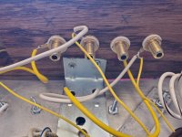
- Did you grind some paint off one foot of each of the OPTs and PT so that their chassis are grounded to the top plate?
Just a few things I would point out.
- It's a really good idea to tin all the wire ends that you are screwing into the board terminals. It will prevent pieces from breaking off and creating short circuits. Honestly it is worth the time/effort to do it. You will almost certainly be wiring this up more than once (I've done mine about 8 times now!). Keep them flat and take it easy on the solder, though. Otherwise they'll be too fat to get two of them into one terminal (like the blue jumper on the OPT connection, for example).
- The Yellow wire extension appears to be a significant gauge reduction from the original from the PT - or is it just much thinner insulation?
- T2-Sec and T3-Sec need jumpers.
- Did you grind some paint off one foot of each of the OPTs and PT so that their chassis are grounded to the top plate?
Last edited:
The yellow wire is a reduction, its 20 gauge. I do have bits of wire I can use from trimming the wires on the output. Was not happy how that turned out, will replace with some of the bits I've cut off. Will go thru and tin the ends to the board as well.
I forgot the jumpers on T2 and T3. That would not have ended well!
I used grounding washers, and ground off paint on one corner of each transformer. Ran a ground to the mounting screw for the Choke, will do the same for the Cap. There is a huge nut on the end of the cap, will find a ring that fits it, and solder a strap to it. Used some aluminum to mount the RCA's to the wood chassis, the aluminum has been grounded, but the RCA's are insulated. Will add a ground to one side of the RCA jacks. I am using the 20 gauge wire for grounding straps, do you think that is to thin?
I can't imagine rewiring 8 times! I'm struggling with the first time, but learning along the way. Everything isnt turning out as neat and tidy as I pictured, can see myself going thru it and making it right. Struggled with wiring diagrams, but think I've figured it out. This color blind thing was getting in the way, so many of the colors look the same to me. Had to print everything out and have someone label them for me.
Thanks again for looking at it for me.
- Status
- This old topic is closed. If you want to reopen this topic, contact a moderator using the "Report Post" button.
- Home
- More Vendors...
- Tubelab
- Duke's Build Thread