Made decent progress today. I realized the values on my auricaps are wrong so i gotta wait for new ones.
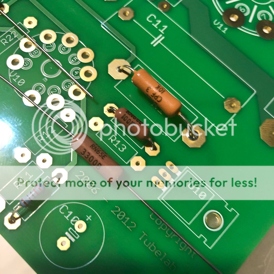
Worried that C3 is too big and that R2 and R14 are too small compared to other pictures I've seen of completed boards but I've checked the specs and they do match. I'll attach my parts list in PDF to another post.
I also installed TR1, D3 and D4.
Worried that C3 is too big and that R2 and R14 are too small compared to other pictures I've seen of completed boards but I've checked the specs and they do match. I'll attach my parts list in PDF to another post.
I also installed TR1, D3 and D4.
_completed_board.jpg?width=1920&height=1080&fit=bounds)
Looking good!
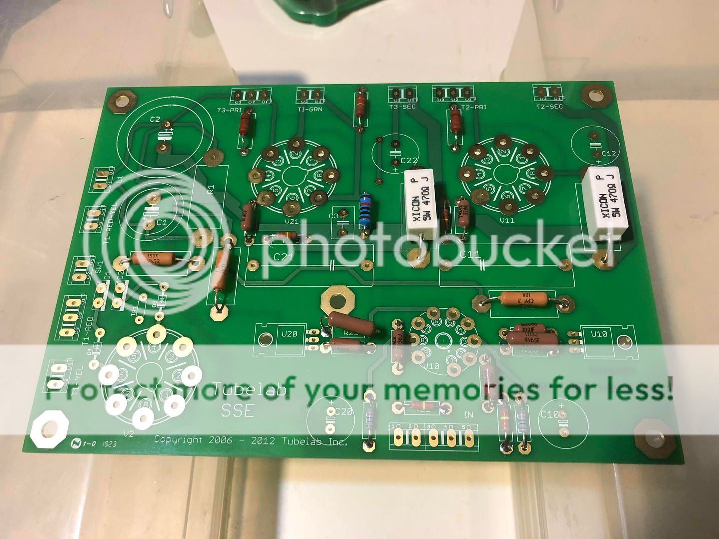
What power transformer and rectification are you planning on using? I am curious because I see you have 470 ohm cathode bias resistors (R17/27). With a typical power supply and rectification setup, that is going to run tubes pretty darn hot. Even 560 ohm (as per the SSE parts list) can result in some very hot tubes under common configurations.
Just something to be aware of.
Looking good!
What power transformer and rectification are you planning on using? I am curious because I see you have 470 ohm cathode bias resistors (R17/27). With a typical power supply and rectification setup, that is going to run tubes pretty darn hot. Even 560 ohm (as per the SSE parts list) can result in some very hot tubes under common configurations.
Just something to be aware of.
Thanks!
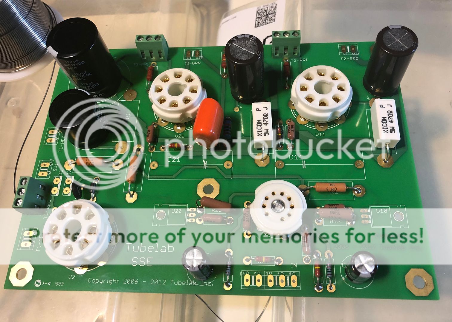
Power transformer will be Edcor XPWR035.
I will have a switch for tube (JJ GZ34/5AR4) or solid state rectification and I plan on using KT88 tubes. I thought I was in the “safe zone” as per the charts on the website.
With KT88 you'll be fine. Those suckers are good for ~40 watts.")
Awesome thanks
So, in my experience, the Vishay/Dale metal film resistors (13 and 23 on yours) tend to be either perfect or long for holes. What you can do is bend them all the way around under the resistor with some needlenose and then make a sharp bend down at the hole. if you get it right they end up sticking out a little more but not a huge amount and the leads are covered so they dont touch anything else.
And KT88s will be fine - thats the setup I put in my first SSE.
And KT88s will be fine - thats the setup I put in my first SSE.
Maybe not exactly the answers you need, but this kit did it for me. https://www.amazon.ca/gp/product/B06XQ33Y9X/
I like having extra stuff like this squirreled away for other projects.
I like having extra stuff like this squirreled away for other projects.
Just a quick question what size are the mounting holes on the board? ... recommendation for how far to stand off if I’m
mounting it to an aluminum plate?
... this kit did it for me. https://www.amazon.ca/gp/product/B06XQ33Y9X/
....
I have this same kit but only used it to mount the soft start PCB I used. For the SSE PCB itself I used some 10-32 screws and spacers. Like you I mounted all parts on top of the PCB. Mine is screwed to the bottom chassis plate using 1" spacers which gives about 1 3/4" clearance between the top of the PCB and top plate. This was enough to clear all parts and leave some room for air to circulate around them.
I have this same kit but only used it to mount the soft start PCB I used. For the SSE PCB itself I used some 10-32 screws and spacers. Like you I mounted all parts on top of the PCB. Mine is screwed to the bottom chassis plate using 1" spacers which gives about 1 3/4" clearance between the top of the PCB and top plate. This was enough to clear all parts and leave some room for air to circulate around them.
Cool thanks so the M3 size is what I want.
- Home
- More Vendors...
- Tubelab
- Birk's SSE Build Thread