A few years back a forum member posited a query about a MOSFET-less TSE, and over the course of a lengthy thread, an SSE with directly heated final amplifier tubes emerged.
Tubelab SE: Removing MOSFETs?
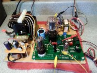
The experimental DH SSE that emerged ( 2A3 finals ) has worked without any component failures or other issue for the last three years. The TSE and TSE II have nothing to fear from that amp, but it is a nice and very simple beginner DH amp nonetheless.
The chassis - a 12 x 10 inch piece of scrap plywood, plucked from a trash pile ( literally ), bugs me. Likewise, the exposed voltage, while acceptable at the time, due to changing circumstances is now unacceptable.
Another thing that has bugged me was the level of damage caused to the SSE PCB to make a DH amp. It's terrific for experimenting, but it's not for the faint hearted builder. Also as part of this thread, will be an attempt to build a DH SSE using readily available, directly heated, tubes that does not damage the PCB in any way - all modifications will be fully reversible.
I hate metal chassis working, even though it is the best choice for an amplifier, imo. I have zero woodworking skills, so that's out. Recent acquisition of some 3D printers has caused me to consider whether or not a 3D printed chassis can successfully support a tube power amplifier, specifically, the experimental DHT SSE and unmodified SSE amps.
Printing a breadboard or complete chassis may or may not work. It may be that the heavy power supply will need to be separated from the main chassis. It may be as simple as a plastic printed plate emulating the breadboard piece of wood, or maybe mounted on an inverted metal chassis, or a nice wood base. Heat from the tubes and power transformer may be a deal breaker. It may be a complete waste of time, plastic and bandwidth.
To start somewhere, I made a template of the SSE PC board, and printed it out, and it looks pretty good, but I don't have a board here at the lake to match it up with and make sure all the holes correspond satisfactorily. It may need some minor tweaking. I made a quick 10 x 12 x 2 inch model chassis ( the same size as my Hammond chassis / cage based child resistant SSE ), with the SSE template embedded, just to get an estimate of the economics. At my current filament price for high temp PLA, the 12 x 10 x 2 chassis would be about ten bucks at 50% infill, and will decline some as more holes are added for transformers, meters, etc. So, it looks like the economics are favorable.
I am still in the middle of another project that has turned out to be more difficult / time consuming than I had anticipated; there will a lot of trial and error involved here; and I can only print the big parts at my office where I have the big printer, so this project will play out over some length of time just like its predecessor, but if you are looking for a reason to build another SSE ( and who isn't? ) this could be that reason.
EDIT 11/27/2020
I have made the pcb template public on TinkerCad, so it can be downloaded and copied for any purpose. It is tagged under "tubelab" and "w5jag" so a search for either tag will bring it up.
This way anyone can download it, ungroup the parts in TinkerCad, and tweak it as needed for their personal printer, or modify it for any other use. I will do likewise with any other models made for this project.
I did this because while it fit to the pcb like a glove when printed on my big 500mm Creality, it was off a bit when printed on my box of parts printer. I suspect the calibration on the factory built Creality is accurate, whereas my box of parts printer is not at this time. So this way folks can tweak it as needed for their printer.
Tubelab SE: Removing MOSFETs?
The experimental DH SSE that emerged ( 2A3 finals ) has worked without any component failures or other issue for the last three years. The TSE and TSE II have nothing to fear from that amp, but it is a nice and very simple beginner DH amp nonetheless.
The chassis - a 12 x 10 inch piece of scrap plywood, plucked from a trash pile ( literally ), bugs me. Likewise, the exposed voltage, while acceptable at the time, due to changing circumstances is now unacceptable.
Another thing that has bugged me was the level of damage caused to the SSE PCB to make a DH amp. It's terrific for experimenting, but it's not for the faint hearted builder. Also as part of this thread, will be an attempt to build a DH SSE using readily available, directly heated, tubes that does not damage the PCB in any way - all modifications will be fully reversible.
I hate metal chassis working, even though it is the best choice for an amplifier, imo. I have zero woodworking skills, so that's out. Recent acquisition of some 3D printers has caused me to consider whether or not a 3D printed chassis can successfully support a tube power amplifier, specifically, the experimental DHT SSE and unmodified SSE amps.
Printing a breadboard or complete chassis may or may not work. It may be that the heavy power supply will need to be separated from the main chassis. It may be as simple as a plastic printed plate emulating the breadboard piece of wood, or maybe mounted on an inverted metal chassis, or a nice wood base. Heat from the tubes and power transformer may be a deal breaker. It may be a complete waste of time, plastic and bandwidth.
To start somewhere, I made a template of the SSE PC board, and printed it out, and it looks pretty good, but I don't have a board here at the lake to match it up with and make sure all the holes correspond satisfactorily. It may need some minor tweaking. I made a quick 10 x 12 x 2 inch model chassis ( the same size as my Hammond chassis / cage based child resistant SSE ), with the SSE template embedded, just to get an estimate of the economics. At my current filament price for high temp PLA, the 12 x 10 x 2 chassis would be about ten bucks at 50% infill, and will decline some as more holes are added for transformers, meters, etc. So, it looks like the economics are favorable.
I am still in the middle of another project that has turned out to be more difficult / time consuming than I had anticipated; there will a lot of trial and error involved here; and I can only print the big parts at my office where I have the big printer, so this project will play out over some length of time just like its predecessor, but if you are looking for a reason to build another SSE ( and who isn't? ) this could be that reason.
EDIT 11/27/2020
I have made the pcb template public on TinkerCad, so it can be downloaded and copied for any purpose. It is tagged under "tubelab" and "w5jag" so a search for either tag will bring it up.
This way anyone can download it, ungroup the parts in TinkerCad, and tweak it as needed for their personal printer, or modify it for any other use. I will do likewise with any other models made for this project.
I did this because while it fit to the pcb like a glove when printed on my big 500mm Creality, it was off a bit when printed on my box of parts printer. I suspect the calibration on the factory built Creality is accurate, whereas my box of parts printer is not at this time. So this way folks can tweak it as needed for their printer.
Attachments
Last edited:
I bought a 3D printer several months back, but due to changing circumstances, it's still in its shipping box.
I therefore have no experience with PLA, but my first Lexan TSE was not really the first...the first was made from some dumpster clear plastic which was "clearly" not polycarbonate, because it melted. OK, it didn't really "melt" but sagged pretty bad after only a few weeks of heat from the tubes.
I ran 45's, NX-483's and 300B's in that amp back then. It has seen only NX-483's in the last 12 years or so.
The Lexan version still looks the way it did when I made it nearly 15 years ago.
I have some clear PLA, but I have not tried it yet. I see that Push Plastic has some of the "high heat" PLA in clear, so I may pick up a spool of it:
Push Plastic High Heat PLA 3D printer filament
I have a spool of the grey high heat PLA, but I haven't tried it since I'm not to that point yet in the other project. The high heat stuff may or may not be necessary here - I'm going to try the ordinary PLA first and see how it works.
For just a breadboard, I don't think heat will be an issue, but it might be for a full enclosed chassis like your Lexan amps, or a 3D printed cage, without some consideration to ventilation.
We'll find out!
I hate metal chassis working, even though it is the best choice for an amplifier, imo.
I have zero woodworking skills, so that's out.
Same for me, and a good option is a laser cut flat metal top plate, on a prebuilt wood base.
Or a local person could build the wood base, lots of woodworkers around. Some examples:
Laser-cut metal parts Shipped Fast | Instant Quotes
HWCHAS1310AL Hammond Mfg. Enclosures | Hawk Electronics
Kalos Wood Amplifier Cases for Valve Tube and Solid State
Last edited:
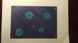
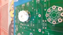
I tweaked the template a bit to give a better correspondence around the tube sockets, and made a partial print of the first five or six layers of the template.
This one looks usable - the holes for the tube bases may or may not need to be opened up a bit for more ventilation, and some ventilation for the 10M45's might be needed.
I tried to edit the first post, but apparently attachments cannot be added or removed, although it looks like the text can still be edited.
Attachments
The predecessor 2A3 SSE was characterized with a Heathkit AA-1 Audio Analyzer ( assembled by me from an unbuilt kit four or five years ago ), but I am going to try to use something a bit more modern on this build.
I got a thing called a Red Pitaya ("RP")
Red Pitaya - Stemlab swiss army knife for engineers
to use in another project, and never really considered using it for audio since I have the aforementioned new AA-1, and a companion HD-1 THD analyzer and Leader audio generator, but it looks like the RP might be useful for audio equipment as well. If it works, a shelf full of equipment can be replaced with something about the size of a pack of smokes.
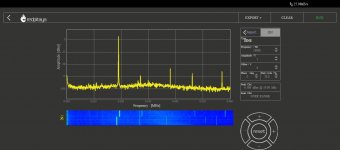
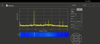
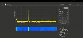
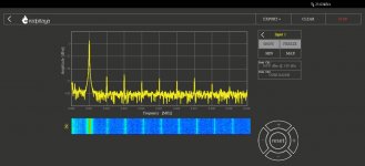
The first screenshot is a 1 volt ( 7dBm ) 1 KHz FFT of the channel one signal generator output looped back into the channel one input, and displayed on the FFT spectrum analyzer function. It looks like about 0.05 - 0.06% THD to me, so should be plenty usable here. I measured my cheap hamfest scrounge Leader generator at about 0.04% with the HD-1, so this seems comparable to my old analog stuff, with the additional advantage of seeing a spectrum distribution instead of just a % number. THD is not hard to calculate, and there are online calculators that can do it from raw numbers.
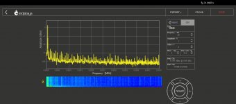
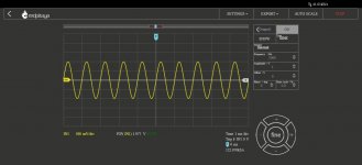
The 1KHz sine wave looks nice as well. The other shots are 60 Hz, 6 Khz, 18 KHz and 19 KHz, all at 1 volt loop back, for two tone IMD testing. I don't understand the value of two tone IMD testing with 18 and 19 Khz tones ( maybe someone can explain it to me ), but the RP can do it, so I guess I will try it. The AA-1 has onboard 60 Hz and 6 KHz tone generators, but I usually used the leader to inject 200 Hz as a low frequency test tone, since the little OPT's I use do not handle 60 Hz very well.
The AA-1 is actually a very useful all in one piece of test equipment even in this era, if you can find a good one at a low price.
I got a thing called a Red Pitaya ("RP")
Red Pitaya - Stemlab swiss army knife for engineers
to use in another project, and never really considered using it for audio since I have the aforementioned new AA-1, and a companion HD-1 THD analyzer and Leader audio generator, but it looks like the RP might be useful for audio equipment as well. If it works, a shelf full of equipment can be replaced with something about the size of a pack of smokes.
The first screenshot is a 1 volt ( 7dBm ) 1 KHz FFT of the channel one signal generator output looped back into the channel one input, and displayed on the FFT spectrum analyzer function. It looks like about 0.05 - 0.06% THD to me, so should be plenty usable here. I measured my cheap hamfest scrounge Leader generator at about 0.04% with the HD-1, so this seems comparable to my old analog stuff, with the additional advantage of seeing a spectrum distribution instead of just a % number. THD is not hard to calculate, and there are online calculators that can do it from raw numbers.
The 1KHz sine wave looks nice as well. The other shots are 60 Hz, 6 Khz, 18 KHz and 19 KHz, all at 1 volt loop back, for two tone IMD testing. I don't understand the value of two tone IMD testing with 18 and 19 Khz tones ( maybe someone can explain it to me ), but the RP can do it, so I guess I will try it. The AA-1 has onboard 60 Hz and 6 KHz tone generators, but I usually used the leader to inject 200 Hz as a low frequency test tone, since the little OPT's I use do not handle 60 Hz very well.
The AA-1 is actually a very useful all in one piece of test equipment even in this era, if you can find a good one at a low price.
Attachments
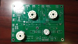
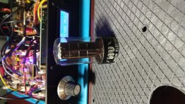
One of the things I had not given any previous thought to is the potentially poor manufacturing tolerance of cheap Chinese tube sockets. I grabbed three octals and one nine pin at random, stuck them in an SSE board, and while hard to tell from the parallax, they do not perfectly center in the outlines on the PCB. The socket stuck in the rectifier position is a particularly bad offender.
Regardless, I think there is enough tolerance in my template to be unaffected by this, although depending on the sockets, it may or may not look perfectly centered when viewed directly from above.
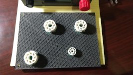
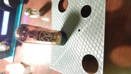
When passing the template over the tube sockets, it looks like it is sized to permit adequate ventilation around the sockets, so long as the template is below the upper surface of the octal tube sockets. Heat rises, so high heat PLA may not be necessary here.
For mounting above the upper level of the tube sockets, it fits the standard octal base and modern coin base like a glove, although heating of the PLA, even high heat PLA, may be problematic for this type of mounting. Fat bottom tubes like 6550 would need a much larger opening.
Tentatively, I think the most recent template is good to go for now.
Regardless, I think there is enough tolerance in my template to be unaffected by this, although depending on the sockets, it may or may not look perfectly centered when viewed directly from above.
When passing the template over the tube sockets, it looks like it is sized to permit adequate ventilation around the sockets, so long as the template is below the upper surface of the octal tube sockets. Heat rises, so high heat PLA may not be necessary here.
For mounting above the upper level of the tube sockets, it fits the standard octal base and modern coin base like a glove, although heating of the PLA, even high heat PLA, may be problematic for this type of mounting. Fat bottom tubes like 6550 would need a much larger opening.
Tentatively, I think the most recent template is good to go for now.
Attachments
When considering how to use directly heated tubes on the SSE, something it was clearly not intended to accommodate, my first thought was that you can’t get there from here. The 20 - 20 hindsight reality is that you can, easily, and anyone who wants an entry level, directly heated amp, should be able to produce a very good one with minimal effort and expense using an entirely unmodified SSE board.
I am not a tube historian by any means, but after De Forrest added the third element to the vacuum diode, a base / socket system with only four pins was entirely adequate for the vacuum tubes of that era, one pin being required for the plate (anode), one for the control grid, and two for the filamentary cathode. Thus, most directly heated tubes exist on a four pin base. As more electrodes were added to the tubes, and indirect cathode heating came to prevail, the number of pins on the base rapidly expanded, first to five, then six, seven, and finally by the mid ‘30’s or so, the eight pin octal base was well established.
The SSE uses the eight pin octal socket, therefore, to accomplish the goal of making a directly heated amplifier without any destructive modifications to the stock PCB, the first iteration of this project will be confined to directly heated tubes with an octal base.
The type 2A3 triode tube evolved into a 6 volt variant, the 6A3. The 6A3, when mounted on an octal base, became the 6B4G. NOS and new production 6B4G is readily available. 2A3 tubes have been proven to work satisfactorily with the existing SSE front end, provided that some component values are changed to reflect the lower B+ voltage that will be used, thus there is really no additional tinkering to be done to make a 6B4G SSE.
The SSE board uses the common 7AC octal tube pinout, The 7AC format assigns the pins as follows:
1. No connection, or metal shell
2. Heater
3. Anode ( plate )
4. Screen grid
5. Control grid
6. No connection
7. Heater
8. Cathode and suppressor grid ( or beam forming plates )
The SSE further incorporates a jumper between pins 1 and 8 making it compatible with the 8ET pinout ( EL34 / 6CA7 ), which brings the suppressor grid, or beam forming plates out separately to pin 1.
The 6B4G uses the 5S pinout. 5S connections are as follows:
1. No connection
2. Filamentary cathode
3. Anode ( plate )
4. No connection
5. Control grid
6. No connection
7. Filamentary cathode
8. No connection
The only conflict between 7AC and 5S are pins 2 and 7. 7AC uses these pins for the tube heater, while 5S uses these pins for the combined cathode and heater of a directly heated tube. Other than the pin 2 and 7 connections, the 6B4 is a drop in tube for the SSE.
In practice, the conflicting uses of pins 2 and 7 is of no consequence. The SSE is a cathode biased amplifier. The directly heated SSE will also be cathode biased. Cathode biased directly heated power tubes, so far as I know, require a separate filament transformer or winding for each power tube, preferably with a center tap, thus the SSE filament circuitry, for the power tubes, is of no use to us anyway, and our directly heated tubes need to be isolated from it.
The captain obvious way of doing this is to just take the tube socket pins for 2 and 7, and bend them up and away from the PCB. All of the other tube socket pins will be soldered to the PCB as normal. The isolated pins on each tube socket will be used as solder points for the leads from that tubes filament transformer; the transformers center tap will be soldered to pin 8, thereby establishing the connection point for the cathode bias. To ensure there is no contact between pins 2 and 7 and the PCB, the socket can be elevated slightly, or some electrical tape or other insulating material can be applied to the exposed pads for pins 2 and 7.
2.5 to 3K would be the usual OPT load, but 5K would work just fine. The cathode resistor will be 750 ohms.
A 300 - 0 - 300 power transformer with a 200 ma current capability should be satisfactory. A 6.3 volt filament winding at about an amp is needed for the 12AT7, and a 5 volt, minimum 2 amp winding is required for the rectifier tube. Each 6B4G tube will require its own 6.3 volt center tap, minimum 1 amp, transformer for its filament / cathode. All of these windings can exist on one core, indeed, the transformer I am using for my 2A3 SSE has the high voltage, 5 volt, and separate 2.5 volt center tap filament windings all on one core. I still have to provide a small filament transformer for the 12AT7.
Conceptually, that’s pretty much it- a really simple project. Other than the 6B4 tubes and a couple of small center tap filament transformers, a DHT SSE is not materially different than building a regular SSE. The component changes needed to the front end are discussed in the linked thread above that begat the original DHT SSE, and I’ll identify them again in a later post.
Attachments
All that said, I’m not going to use 6B4G in the directly heated SSE I’m going to build in this thread. The 2A3 SSE is been there, done that, and on top of that, I haven’t been able to scrounge any 6B4G tubes locally.
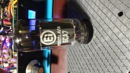
So I’m going to use a more obscure directly heated octal - the type 1619. The type 1619 is an RF beam power tetrode, on a type 7AC base, EXCEPT that it has no cathode - the beam forming plates are brought out directly to pin 8. The filamentary cathode is the usual 2.5 volts, and I already have some 1619 tubes, so I don’t have to buy anything new, except for maybe some better OPT’s. Type 1619 will use a 7 to 8K OPT, and since it has extra grids, playing with pentode and distributed load / ultra linear will be possible.
Some people say that the 1619 is a poor mans 45. I find that hard to believe since one is a triode, and the other is an RF beam tetrode, but whatever. I guess we will find out what 1619 can do in due course.
Right now my point of indecision is the 3D printing aspect. I have a 500 x 500 mm printer, so I can print pretty much a full size anything, but the usual printer is in the 220mm x 220mm, maybe a bit bigger, size. So I'm thinking about doing it in pieces to start with, so there will be SSE models available for ordinary size printers.
That would mean putting the power transformer on a separate chassis, and maybe the choke. Ordinarily, that would be of no consequence, but since each power tube has its own filament winding, that will mean some pretty long leads in the cathode bias circuitry for the amp. I'm not sure if that will cause any adverse effect or not.
This is all very cool! More than anything, it has got me thinking about getting a 3D printer. My wife and kids keep bugging me to make a Christmas wish list. ")
The thing is, where do I even begin to figure out what I want to get? I started looking on Amazon and found the Creality Ender-3 Pro. I like the fact that it is open source and built with off-the-shelf parts. I plan to use Linux, running (I think) Ultimaker Cura software.
Is there a good source of info for all things 3D printer?
Last edited:
I think 3D printers are about the neatest thing since sliced bread, but as a non technical person, I have found them to be a substantial learning curve. I am very far from knowledgeable about them.
First, there is the printer itself.
Then, you have to get a model from somewhere, or if one does not exist, you have to make your own or modify an existing model. This means learning elementary CAD work. Making my SSE "models" downloadable from TinkerCad is like handing someone source code - they can freely modify ( aka fix my mistakes ) the models.
Finally, there is the slicer program that takes the 3D model and "slices" it into a bunch of 2D parts printed one on top of another, and spits it out in a machine code the printer can use to run the steppers. These programs may be the most complicated part of the whole deal.
If there is an all in one site for all things 3D, something along the lines of 3D Printing for Dummies, I would be interested in knowing about it as well.
I think any of the Creality printers would be a good choice; they come as a knockdown kit and assemble in an hour or so, and look to be reasonably good quality. Just make sure it has a heated print bed. I think all of the Creality do, but some box of parts printers may not. I have a CR10S-5 (500 x 500 x 500 mm ) at the office. I can say that the Tronxy P802 "box of parts" 3D printer at our second house has taught me quite a bit abut these things, and has helped move me along the learning curve.
I have turned out some really, really, crappy looking stuff so far. I expect to turn out more crappy looking stuff over the course of this project before it's done, but all of these interlocking parts - printer, CAD, and slicer - are finally beginning to converge for me, so I'm looking forward to see if 3D printing is going to be useful for this type of DIY electronics.
The little printer here at the lake is only 220 x 220 mm which puts a practical limit of about 215 x 215 mm, more realistically closer to 210 x 210 mm, on anything created by it in a single piece. The Merit P-2968 power xfmr and SSE PCB cannot both fit in this space, not to mention the other iron needed, necessitating a two box solution if I use this xfmr.
A two box solution requires 16 interconnections with the main chassis, 7 of which have high voltage. If I move the rectifier and most of the B+ parts to the power supply box, I can reduce this to 10 interconnections, only one of which is high voltage. I'm not real familiar with current connector options that can also handle high voltage. AFAIK, the standard is to have the female connector on the power supply end, to reduce the risk of accidental electrocution if the cable gets disconnected while the power supply is live.
It looks like the classic Cinch-Jones connectors are still available in a 16 pin configuration, but the 16 pin shrouded female cable connector is expensive. The 16 pin male chassis connector is cheap. I think I might be able to make a cable shroud with the printer, and use a 16 pin female chassis connector on the power supply cable, that would still be safe. That would cut the cost of the Cinch-Jones parts by about two thirds. I think 18 pin parts are also available, which could leave two pins as a safety to kill the power supply if it became disconnected from the amp.
10 interconnects are easy to manage. The old school 11 pin Amphenol style cable and chassis connectors used in tens of thousands of ham radio sets are still readily available, at about the same cost as the Cinch-Jones parts, i.e not cheap if you're a tight fisted hobbyist ( I am ).
Finally, I guess octal chassis sockets and octal tube bases would also work. That is probably the least expensive and least desirable alternative, since it would require two cable sets. I might go this route, since I already have suitable chassis mount octal sockets on hand. The holes will be printed anyway, so it's not like it is any extra effort to double the number of holes that have to be made. Two cables obviously makes it easier to hook the cables up wrong. w5jag's law says that will eventually happen without some type of safeguard.
Interestingly, I was looking at / pricing out available xfmrs yesterday, and I think I could get everything on one 215 x 215 mm chassis if I am willing to disregard some of the traditional chassis layout norms. That would also require buying a bunch of transformers I don't presently have, which I am trying to avoid - I'm trying to keep the new iron acquisition limited to just some new 8K ish OPT's.
If I go with a single box solution, it will be 12 x 10 inch, the same size as the existing child resistant SSE ( still running strong coming up on seven ( 7 ) Years now ), and the existing DHT SSE breadboard in post #1. It is very easy to get everything in a chassis that size, with quite a bit of room to spare.
I almost ordered some new Edcor OPT's yesterday, but the shipping charges just really rub me the wrong way. It looks to cost as much as a single transformer to ship a pair of OPT's to me - and I'm only two states away from the factory. I may try to get a price on some Transcendars since he is winding again. I have some 7K OPT's right now, they're just not very good. And I have some Hammond 125ESE OPT's I'm not using at the moment. Actually, I have a lot of OPT's I'm not using right now- I just don't have the ones I want / need for this project.
I'm sure it could be done, but I don't know what kind of structural rigidity one might get from it. And given the weight of even modest iron parts, I think high rigidity is a requirement. ( edit: ) I'm also trying to avoid visible fastners as much as possible - take that away, and more options are available.
A possibility / work around might be to use some of the parts that would ordinarily be fastened down, like the OPT's, as structural components of the "design" to join pieces together and add some rigidity to the complete structure.
Because I have another 500 x 500 mm printer, I've not given much thought to making big parts on a small printer, since I have a big printer for that.
But it's an interesting concept, and worth some thought being put to it - I'm obviously still in the all talk, no action stage at this point.
Last edited:
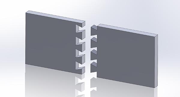
Okay, FWIW, I made a quickie "overlapping" chassis, and made it public in TinkerCad, so anyone can look at it and play / change / fix / break / modify it. Same #tags as the other pieces.
It would print out to about 200 mm x 360 mm ( 8 ish x 14 ish inches ), so, not huge, but plenty usable and a lot bigger than you would otherwise get off one of the little printers.
It (should have) has a 20mm overlap on the top plate, and I put 4 dowel post holes in the side walls that can have dowels pressed in for friction fit, or glued for strength, and some printable dowels to fit, to stabilize the sides.
It may or may not work - someone would have to print out enough of it to find out, and check the fit. It might ( or might not ) be best to flip the underlap piece 90 degrees on end and print it vertically, to avoid having to print support under the underlap. In that instance, the dowel holes on that piece could be made solid, and printed as posts to interlock to the other piece. It will probably probably require a tiny bit of light sanding on the overlap or underlap and dowels / posts to get a "perfect" fit.
More sanding if the underlap is printed with support under it. Unfortunately, gravity refuses to allow printing stuff that is hanging out in free space.
It may be that the underlap / overlap is a poor / dead end idea, and better ease of print and maybe better rigidity could be obtained with post holes and dowels similar to the side walls. Might not look as good, though.
Some experimenting will be required.
3D design interlocking chassis | Tinkercad
Last edited:
- Home
- More Vendors...
- Tubelab
- 3D printed SSE parts and another DH SSE