Yes, two adjacent boxes with matching support walls with pass-through holes.
If this was the case, the dovetails interlocking the top surface would have almost zero load.
The side connections (where the two boxes meet at each side) could be interlocked with a "dovetail key". Difficult to explain, but I will see if I can draw it...
The dovetailing might look more interesting than a straight butt-joint (like the overlap) but this is a matter of personal taste.
Last edited:
You're also describing a "modular" SSE.
The SSE pcb, controls, switches, meters, etc., go in one box. The front box.
Power xfmr, OPT's, chokes, etc., go in one or more boxes. Call this the "power" box.
Put connectors on all the wiring, and to make a new amp, say change from KT88 to 6V6, just swap out the power box.
As long as a plastic chassis works. Still a big if.
In my mind, the two boxes are epoxied together to form a single chassis, once the parts are pre-tested for a nice fit.
All wiring would then be permanent.
I am not saying the modular idea is bad. In fact, this could be designed with both options in mind.
Question: is it possible to fit SSE + OPTs on one module/box?
All wiring would then be permanent.
I am not saying the modular idea is bad. In fact, this could be designed with both options in mind.
Question: is it possible to fit SSE + OPTs on one module/box?
Last edited:
By the way, I don't want to talk you into going in some other direction. I just love brainstorming about stuff like this.
Also, I have my concerns about this much heat near 3D printed parts. My concern is probably misguided by my lack of knowledge - I am just guessing that this plastic has quite a low melting point.
Also, I have my concerns about this much heat near 3D printed parts. My concern is probably misguided by my lack of knowledge - I am just guessing that this plastic has quite a low melting point.
Last edited:
... The dovetailing might look more interesting than a straight butt-joint (like the overlap) but this is a matter of personal taste.
I'm thinking of using the OPT frames to hide the majority of the butt line.
... Question: is it possible to fit SSE + OPTs on one module/box?
Depends on the size of the available printer. On my 500 x 500 at home base, space / volume is not an issue. On the 220 x 220 I have here at the lake, which is about the average size printer, it's the most important issue.
If you look at the other chassis I have on TinkerCad, the 215 x 215 one, you can see the big open hole to merge in the SSE PCB template. So you can see how much of the available space that pcb takes - quite a bit of it. In the left over space, you can see the hole patterns for some 10 watt open frame Edcors. The 15 watt open frame, and possibly the 25 watt open frame would also fit. I suspect the 10 and 15 watt GXSE transformers would also fit.
So, yes. Even on the small printers, you can get both on one box.
... Also, I have my concerns about this much heat near 3D printed parts. My concern is probably misguided by my lack of knowledge - I am just guessing that this plastic has quite a low melting point.
PLA prints at about 190 C and above. So certainly it will turn fluid if it gets hot enough. Whether the PLA will work, or not, remains to be determined. My gut feeling is that it will work with reasonable planning, but I've had PLA objects deform just from being left in my car. It was summer, and Arkansas, but I didn't expect that.
There is such a thing as high heat PLA, that has better heat resistance qualities after it has been printed, and I have a kg of it that I got to use in another project, hopefully to avoid the car deformation problem ( haven't got to the point in that other project where it is ready to be installed in the car).
So all of this remains to be determined.
Last edited:
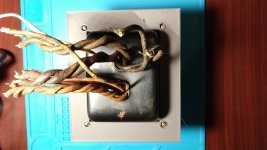
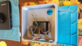
I removed the power xfmr from the DHT SSE, so I could make a template for it.
The xfmr is a Merit P-2968, and is a pretty good chunk of iron: it's 3.75" H x 4.5" W x 3.8125" D; rated 400-0-400 at 110 ma, 5 at 3A, 2.5CT at 3.5 A, and 2.5CT at 15 amps. It was a stock catalog item for Merit, but I can't imagine what it's original application might have been that required a 15 amp secondary.
I've found it best to make templates for the various bits that can then be printed out and tested for correct fit and adjusted as necessary - this helps eliminate the possibility of making a long print using a lot of filament, and finding out it is not quite right when it is finished.
Anyway, the P-2968 template looks to be a good fit and ready to drop in a chassis. This thing is really heavy and runs hot, so should be a good test article.
Attachments
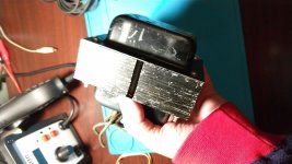
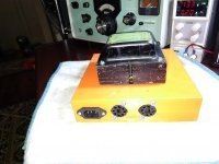
So, here is power supply test article number one.
This was printed here at the lake, on the $100 USD box of parts printer, with ordinary PLA, 0.2mm layer height, 50% cubic infill, at 50 mm/second speed.
It's not a thing of beauty, but looks satisfactory for the immediate purpose as an experiment / test mule. It may look a bit better when the support remnants are cleaned out of the holes. Or it may not. But it's a start; you have to start somewhere. The article used about $4 USD worth of plastic and printed overnight into mid morning.
The deck and side walls are 5mm and physical strength appears to be completely satisfactory even with this very heavy transformer, at least with the transformer cold. At operating temperature may or may not be different, but I still have the earlier print out of the test transformer template that can be used as a strengthener or spacer if need be.
The overall height is 50 mm ( 45 mm usable ) and this looks to be marginal for vertical mounting an IEC connector, and for interior parts guts. I like things compact and low profile, but article two will likely be at least 60 mm overall height, maybe taller.
I put a rectifier tube socket hole in the top, which I will likely install to see how the ordinary PLA responds to the heat source, since rectifiers run with the heat of all the B+ going through them. I added a hole for some choke leads, but am not sure what choke I will be using, so I left mounting holes out.
I may skip a choke, and use something more modern like a MOSFET ripple filter. I am also leaning toward using the 5 vac taps on the power supply to power the 12AT7; this would eliminate one transformer, but require using something like 6AX5 as the rectifier, which was proven very satisfactory in the child resistant SSE. Or sand.
I probably won't do anything else on it over the weekend; I brought my RF travel kit ( a 16 inch tool box ) to the lake with me, and it is almost completely SMD / SMT parts, not a lot of through hole since they take up so much space, even in the smallest form factors. I am making up a high voltage / electron tube travel kit, but getting a decent variety of parts in it, considering the physical size of OPT's, power transformers, tube sockets, leaded parts, etc., is challenging. In any event, I left it back home.
Attachments
")
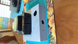
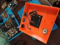
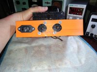
So, test article 1 was certainly strong enough - I could stand on it without stressing it, but the 5 mm top and side thickness made it difficult to mount the other stuff in a cosmetically acceptable way.
Test article 2 is constructed differently, it has extra strength over the top and sides where the heavy pwr xfmr is located, but the rest of the article is substantially less robust - about 2 mm. I also used considerably less infill - 20 %.
It looks and feels adequate, but for one issue - the plastic between the two octal sockets on the rear panel simply failed to fuse for unknown reasons. From a cosmetic standpoint, the rear panel is the place to have an issue, if one occurs. From a structural standpoint, it is a bad place and there is a real possibility that this will be a significant issue. I put some glue into the delam spot to try and stabilize it, but that may or may not be helpful.
I don't know that I will get a chance to wire on it tomorrow. Print time was about 26 hours. Material cost about $4 USD.
Attachments
Not a good DIY day.
Worked some in the morning on another project - nothing worked even close to satisfactory.
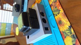
So I decided to wire the power supply for this project. When I went to mount the front panel on / off switch, it would not fit. Checked the dimensions in the tinkercad model, and those dimensions were wrong, at least for the switch I wanted to mount today.
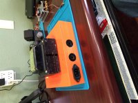
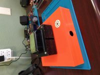
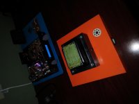
When that was "fixed", I decided I had to deal with the back panel around the octal sockets where the plastic did not fuse. The original intention was that the sockets would fit tightly enough so that no mounting hardware was necessary, which is not possible at present. Unplanned and hastily conceived plan B ( for "bodge" ) was to use mounting hardware, and, as I was drilling out the fourth of four holes, you guessed it - the weak back panel split from the edge of the IEC connector all the way to the opposite edge of the panel. Since I was trying to stabilize the brittle plastic with my finger while I was drilling, I also managed to drill a hole in my finger.
After I got the bleeding mostly stopped, I stuck the sockets in, screwed the mounting hardware in, and sat it on the desk and admired the wide split running almost the full length of the panel, about 1/8 inch ( 3+ mm ) wide at its maximum, while I kept the compression on my finger.
As I thought about whether or not this train wreck could be salvaged, or if I was going to have to start over and print test article 3, and what changes I would make, I was drawn to the SMD/SMT rework hot air gun sitting behind the disaster. It occurred to me that the model plastic starts out solid from a reel, it gets heated to about 200 C ish in the extruder, and then it cools again to a solid after it has been deposited. So why not just reheat it?
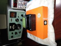
That idea actually worked, sort of. I set the gun to 200 C, and carefully heated the plastic while applying pressure to close the fissure. I also solidified the plastic in between the octal sockets. The result is not pretty, but it became acceptably solid enough for me to go ahead and mount the rest of the hardware and continue on with this test article.
In the pictures, you can still see much of the length of the fissure. It looks in the picture to still be there, but this is a shadow as the edges are offset from each other a little bit. The result was actually much better than I expected - I was resigned to throwing it in the trash ...
The transformer is spaced just slightly above the chassis on some nylon spacers so that air can flow around it. Should be able to get it wired and see how the chassis holds up to heat pretty soon.
Worked some in the morning on another project - nothing worked even close to satisfactory.
So I decided to wire the power supply for this project. When I went to mount the front panel on / off switch, it would not fit. Checked the dimensions in the tinkercad model, and those dimensions were wrong, at least for the switch I wanted to mount today.
When that was "fixed", I decided I had to deal with the back panel around the octal sockets where the plastic did not fuse. The original intention was that the sockets would fit tightly enough so that no mounting hardware was necessary, which is not possible at present. Unplanned and hastily conceived plan B ( for "bodge" ) was to use mounting hardware, and, as I was drilling out the fourth of four holes, you guessed it - the weak back panel split from the edge of the IEC connector all the way to the opposite edge of the panel. Since I was trying to stabilize the brittle plastic with my finger while I was drilling, I also managed to drill a hole in my finger.
After I got the bleeding mostly stopped, I stuck the sockets in, screwed the mounting hardware in, and sat it on the desk and admired the wide split running almost the full length of the panel, about 1/8 inch ( 3+ mm ) wide at its maximum, while I kept the compression on my finger.
As I thought about whether or not this train wreck could be salvaged, or if I was going to have to start over and print test article 3, and what changes I would make, I was drawn to the SMD/SMT rework hot air gun sitting behind the disaster. It occurred to me that the model plastic starts out solid from a reel, it gets heated to about 200 C ish in the extruder, and then it cools again to a solid after it has been deposited. So why not just reheat it?
That idea actually worked, sort of. I set the gun to 200 C, and carefully heated the plastic while applying pressure to close the fissure. I also solidified the plastic in between the octal sockets. The result is not pretty, but it became acceptably solid enough for me to go ahead and mount the rest of the hardware and continue on with this test article.
In the pictures, you can still see much of the length of the fissure. It looks in the picture to still be there, but this is a shadow as the edges are offset from each other a little bit. The result was actually much better than I expected - I was resigned to throwing it in the trash ...
The transformer is spaced just slightly above the chassis on some nylon spacers so that air can flow around it. Should be able to get it wired and see how the chassis holds up to heat pretty soon.
Attachments
Win W5JAG is obviously a My Brother by A Different Mother.
I actually drilled a hole in my THIGH when mounting drawer hardware on a bottm kitchen drawer. Holding the drawer in place with my bended knee, drilling through the front panel, caught the thigh skin tangentially and ripped off a large chunk of dermis.
Fortunately, I get Frequent Flyer upgrades from the ERs around town, and drew a Johns Hopkins trained Trauma Surgeon. Best suture job I've even seen. Scar disappeared after about a year.
I like to think that I was the inspiration for my daughter becoming an ER doc...snort.
[Really, just posting to subscribe to this thread, for both (a) 3D printing and (b) SSE board hacks. Already done a bunch of (b), and of course been noodling on (a) for two or three years.]
Interesting project. While I might not modify my SSE I still would like to try some DHT build one day, together with outputting to solely a Full-range set of speakers instead of cross-overed two-way ones.
I Dremeled into my finger through a home-etched PCB once. It hurt a little.
I Dremeled into my finger through a home-etched PCB once. It hurt a little.
Guy's you are not trying hard enough. I have cut, Dremeled, drilled, and even tried to solder my fingers into a circuit a few times. Not to mention electrical shocks or dripping molten solder onto legs and feet......but you haven't lived until you douse yourself in gasoline, set yourself on fire, then RUN.
I have unfortunately done all of these more than once, except for the fire thing....once is enough for that trick.
I was about 18 years old and had acquired a beat up 1965 Pontiac Grand Prix for cheap. I had taken the carburetor off to find that someone had glued the gasket to the manifold, so I had begun the task of removing it with a paint scraper and some gasoline. Anyone remember the gasoline cans of the 1960's?
Do you know what happens when you accidentally set a metal gas can on top of the car's battery? Flash, bang, and poof. In an instant myself, the car, and everything in sight was on fire. Despite all of the crap I had been told about drop and roll, instinct took over and I ran due south at warp 5. Why? Because the lake was about 100 feet in front of me.
Soon after the immediate dunk had quenched my flames, I realized that the car and the ground underneath it was still very much on fire. I grabbed the garden hose and attempted to drown the flames. This did a good job of moving much of the fire from the front yard to the street in front of my house. Somewhere I realized that the wiring harness was fried and the battery was doing it's best to keep on frying all of that melted mess so a quick hammer disconnect was used.
Somehow I got the fire out....or all of the available gasoline had burned. I had some minor burns, and lost most of my hair, but all healed in good time.....several years later my long hair would meet the fan belt of a running 440 magnum, but that's a different painful story.
It took about 2 months, a lot of wire, and several rolls of electrical tape, but I did manage to get the car running again. All of the fancy vacuum operated AC vents were simply wired open. Full AC was needed in a dark colored car in Miami nearly all year round anyway.
Attachments
w5jag
A few points:
1. I purchased two 10S units. One came out of the box nice, the second the platform was loose. I had to adjust the three wheels underneath that have eccentric cams. To check this, try rocking the platform by holding the sides and alternating up/down rocking.
2. The printhead will eventually loosen a tad, you can see this by lightly holding either of the two top wheels, if they easily can be stopped, you will not have total control over the height.
3. Check the bowden clamps. They tend to loosen with time and the tube will pull up during retractions.
4. I've tended to 220C nozzle temp/70 C bed temp for the build plate I'm using. Tape will not work that high, it pulls right up. Ender 3 build plates are more delicate, those temps can cause adhesion to be too high for the stock ender3 build plate. I migrated to these temps to keep the corners of the build adhered well, without the walls curving the surface of f the plate.
5. You may want to do a cal run on the extrusion factor, my two enders would give 95mm for a 100 mm length extrusion.
6. With bowden systems, after a retraction, when the PLA is pushed again, the printhead may not be hot enough to keep up with the acceleration of the head, so higher nozzle temp may help there.
For the design:
1. You should put recesses at all the xfmr screws for washers. On one of the screws, you need to bond the screw to safety ground. Also verify that the transformer shell has continuity to the screws.
2. I would recommend putting ribs in under the transformer for strength against gravity. PLA will creep over time.
3. Using a minkowsky function can give you nicely rounded corners if you wish.
I use openscad, so referenced that with minkowsky.
If you can, make smaller test pieces to play with parameters to fix the hole bonding issues.
Nice work, I like it.
jn
... several years later my long hair would meet the fan belt of a running 440 magnum, but that's a different painful story.
I can imagine several different outcomes from something like this, loss of a lot of hair being the best case scenario.
When I was a green up to the gills new lawyer, 23 years old and fresh out of school, I handled a case where a young woman had been in an older man's drag boat, that had an exposed drive shaft and universal joints. The young woman's long shirt sleeve somehow got snagged and solidly engaged by one of the u joints. The wind up removed her arm at the elbow.
I grew up around airplanes and had lots of jobs as a kid where moving parts could kill or seriously injure me, but that was a real sobering case to handle. After that, I wouldn't open the hood on my car until after I removed my necktie. Have that habit to this day ...
Hi jneutron
Thank you for the tips; I have two 3D printers but haven't really had that much time to play with them. I have a cheap box of parts ( 220 x 220 ) printer at our second house that I seem to use the most. I did not expect that they would come with a learning curve, but clearly they do.
My 10S at my office is actually a 10S5 which has the 500 x 500 buildplate, which sounds cool at first since you can print really big stuff, but has its own problems just from sheer size.
I *think* I have and am keeping everything tight on them. The mechanical alignment, to be honest, I'm not sure about. My CR10S5 came with essentially no instructions and most of the stuff I see on the internet is not all that clear to me. I finally went to Harbor Freight and bought a micrometer, and spent a lot of time trying to mechanically square and set everything to what I think looks to be about correct. This made a BIG difference on my $100 box of parts printer, and some improvement on the 10S5, but not as dramatic.
Both still show that clearly visible banding or ringing that I have not figured out how to get rid of, but clearly should not be there, and detracts quite a bit from the cosmetic appearance of the printed part.
I have found that the best bed material is polypropylene. Smooth as glass, shoot it with a little Aqua Net hairspray and stuff sticks to it like tape. The cost of it looks to have skyrocketed however. I got a 220 x 220 piece for less than $20 for the box of parts printer, but last I looked it was a lot more than that, and hundreds of dollars for a 500 x 500 piece. So I don't have a 500 x 500 piece; I'm still using the borosilicate glass that came with it.
The 10S5 is very difficult to keep all four corners adhered during a print. The bed is 500 x 500, but the heater is only 300 x 300, so uniform heat temperatures across the bed are difficult to establish and maintain. Because of this, I have migrated to lower bed temperatures ( 50 C ish ) to try to keep a uniform temp on the bed, with long heat soak times prior to printing. I have a cloth shroud I keep around it to try to keep the heat in. I use a brim around the part, and when the brim is printed, I tape the brim down to the glass. These measures are only intermittently successful. I'm open to any and all suggestions on this.
After switching to polypropylene, I have not had an adhesion issue on the little 220 x 220 printer.
Round parts are coming out round on the 10S5. The box of parts definitely needs calibration, but the printer mainboard and my computer resist all efforts to talk to each other. I have an XP machine that may talk to it, but I have not tried that yet. I have not tried to talk to the 10S5.
I will try this.
When I print the amp chassis, or if I reprint the power supply chassis, I'll do that. edit: On this piece, I have nylon washers above and below the chassis for the transformer mounting screws and nuts.
Agreed. Being that it is a plastic chassis, ground considerations are the exact reason I have not wired this piece yet. I was going to connect the ring around the rear octal sockets to safety ground since I can come in to contact with the screw(s), and run another bond wire from each metal part that I can contact to safety ground. I've already thought about continuity from the top transformer shell through the mounting screw, and the answer is that I have not tested for that yet, so it may or may not be a problem.
I'm also trying to decide on a choke or MOSFET ripple filter.
I am open to any and all ideas here for grounding.
I've thought about that. This is partly an exercise to learn the structural limits of what can be done, and how to do it, with cheap 3D printers and tube stuff, so I'm actually okay with failure on these early parts.
OK, I studied agriculture ( animal science ), and then law. I'm still struggling with TinkerCad ...
Learned this the hard way - I now make a template for everything that needs fitting. I test print the templates, and then when they are known to fit I TinkerCad around that. I'm starting to get a library of known to fit stuff.
I'm trying to make these parts fit in a 220 x 220 build plate since that is the most common size printer. The power supply chassis is 200 x 200 OD. The recent orange part was printed on the 10S5.
I am a complete newb at this and open to any and all suggestions - thank you for these.
Thank you for the tips; I have two 3D printers but haven't really had that much time to play with them. I have a cheap box of parts ( 220 x 220 ) printer at our second house that I seem to use the most. I did not expect that they would come with a learning curve, but clearly they do.
... 1. I purchased two 10S units. One came out of the box nice, the second the platform was loose. I had to adjust the three wheels underneath that have eccentric cams. To check this, try rocking the platform by holding the sides and alternating up/down rocking.
2. The printhead will eventually loosen a tad, you can see this by lightly holding either of the two top wheels, if they easily can be stopped, you will not have total control over the height.
3. Check the bowden clamps. They tend to loosen with time and the tube will pull up during retractions.
My 10S at my office is actually a 10S5 which has the 500 x 500 buildplate, which sounds cool at first since you can print really big stuff, but has its own problems just from sheer size.
I *think* I have and am keeping everything tight on them. The mechanical alignment, to be honest, I'm not sure about. My CR10S5 came with essentially no instructions and most of the stuff I see on the internet is not all that clear to me. I finally went to Harbor Freight and bought a micrometer, and spent a lot of time trying to mechanically square and set everything to what I think looks to be about correct. This made a BIG difference on my $100 box of parts printer, and some improvement on the 10S5, but not as dramatic.
Both still show that clearly visible banding or ringing that I have not figured out how to get rid of, but clearly should not be there, and detracts quite a bit from the cosmetic appearance of the printed part.
4. I've tended to 220C nozzle temp/70 C bed temp for the build plate I'm using. Tape will not work that high, it pulls right up. Ender 3 build plates are more delicate, those temps can cause adhesion to be too high for the stock ender3 build plate. I migrated to these temps to keep the corners of the build adhered well, without the walls curving the surface of f the plate.
I have found that the best bed material is polypropylene. Smooth as glass, shoot it with a little Aqua Net hairspray and stuff sticks to it like tape. The cost of it looks to have skyrocketed however. I got a 220 x 220 piece for less than $20 for the box of parts printer, but last I looked it was a lot more than that, and hundreds of dollars for a 500 x 500 piece. So I don't have a 500 x 500 piece; I'm still using the borosilicate glass that came with it.
The 10S5 is very difficult to keep all four corners adhered during a print. The bed is 500 x 500, but the heater is only 300 x 300, so uniform heat temperatures across the bed are difficult to establish and maintain. Because of this, I have migrated to lower bed temperatures ( 50 C ish ) to try to keep a uniform temp on the bed, with long heat soak times prior to printing. I have a cloth shroud I keep around it to try to keep the heat in. I use a brim around the part, and when the brim is printed, I tape the brim down to the glass. These measures are only intermittently successful. I'm open to any and all suggestions on this.
After switching to polypropylene, I have not had an adhesion issue on the little 220 x 220 printer.
5. You may want to do a cal run on the extrusion factor, my two enders would give 95mm for a 100 mm length extrusion.
Round parts are coming out round on the 10S5. The box of parts definitely needs calibration, but the printer mainboard and my computer resist all efforts to talk to each other. I have an XP machine that may talk to it, but I have not tried that yet. I have not tried to talk to the 10S5.
6. With bowden systems, after a retraction, when the PLA is pushed again, the printhead may not be hot enough to keep up with the acceleration of the head, so higher nozzle temp may help there.
I will try this.
1. You should put recesses at all the xfmr screws for washers.
When I print the amp chassis, or if I reprint the power supply chassis, I'll do that. edit: On this piece, I have nylon washers above and below the chassis for the transformer mounting screws and nuts.
On one of the screws, you need to bond the screw to safety ground. Also verify that the transformer shell has continuity to the screws.
Agreed. Being that it is a plastic chassis, ground considerations are the exact reason I have not wired this piece yet. I was going to connect the ring around the rear octal sockets to safety ground since I can come in to contact with the screw(s), and run another bond wire from each metal part that I can contact to safety ground. I've already thought about continuity from the top transformer shell through the mounting screw, and the answer is that I have not tested for that yet, so it may or may not be a problem.
I'm also trying to decide on a choke or MOSFET ripple filter.
I am open to any and all ideas here for grounding.
2. I would recommend putting ribs in under the transformer for strength against gravity. PLA will creep over time.
I've thought about that. This is partly an exercise to learn the structural limits of what can be done, and how to do it, with cheap 3D printers and tube stuff, so I'm actually okay with failure on these early parts.
3. Using a minkowsky function can give you nicely rounded corners if you wish. I use openscad, so referenced that with minkowsky.
OK, I studied agriculture ( animal science ), and then law. I'm still struggling with TinkerCad ...
If you can, make smaller test pieces to play with parameters to fix the hole bonding issues.
Learned this the hard way - I now make a template for everything that needs fitting. I test print the templates, and then when they are known to fit I TinkerCad around that. I'm starting to get a library of known to fit stuff.
I'm trying to make these parts fit in a 220 x 220 build plate since that is the most common size printer. The power supply chassis is 200 x 200 OD. The recent orange part was printed on the 10S5.
I am a complete newb at this and open to any and all suggestions - thank you for these.
Last edited:
I can imagine several different outcomes from something like this, loss of a lot of hair being the best case scenario.
My very fine hair was my salvation. The belt grabbed a bunch which slapped my head hard against the fan shroud causing some blood and hair loss. Then I stood there stupidly watching this blonde wad of hair zipping around under the hood of a 1968 Plymouth Gran Fury, another $200 car I rescued from the scrap yard. After I beat it to death, the motor and trans went into a friends Road Runner.
A high school buddy missing a bit of common sense and his dad stuffed an automotive V8 engine into an air boat where the Lycoming aircraft engine formerly resided. Long hoses and pipes ran to a radiator up front. I refused to ride in it with him partially since he wrecked several cars before graduating high school, and lost his job at Xerox due to bad driving, and partially due to my fear that a hose or radiator would burst scalding everyone on board. It turned out to be a low hanging tree into a less than optimum DIY fan shroud that put a couple people into the hospital and ended the boats life.
The V8 into an airboat did turn out to be a popular conversion several years later once some decent kits became available. I think one came from the Chevy V8 into the back seat of a Corvair conversion people. Crown Conversions maybe?
- Home
- More Vendors...
- Tubelab
- 3D printed SSE parts and another DH SSE