Hey everybody!
I have built a couple of guitar amps in the past, but the SSE is my first foray into HiFi amp building.
I started the build back in March. When I ordered the transformers from Edcor, I had them shipped to Sumas WA, just across the border from me (I'm a Canuck). Unfortunately, they arrived a few days after COVID shut down the border... The project went on the shelf as I not-so-patiently waited for the border to reopen. And waited...
Eventually, I gave up and managed to find a cross-border shipping company/broker to bring the transformers across the border.
Finally, I was able to throw it all together for a test run (a proper enclosure will follow). There were no issues that I noticed upon initial power-up, and the amp sounds great! I am currently running the amp in triode mode with no feedback.
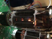
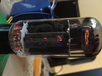
However, I did notice that my power tube screen grids are glowing (EH 6CA7EH). Not an even glow across the whole grid, but only on a few of the grid filaments. Is this possibly a sign of faulty tubes, or due to the fact that the tubes are running quite close to their max dissipation? I don't see any signs of red-plating.
Vk=38V Rk=560ohm Ik=67.9mA Vak=377V (Total dissipation=25.6W)
The 100ohm grid resistor is dropping 0.95V for 9.5mA grid current, which works out to 3.57W of grid dissipation (which is safely below the 8W rated for this tube).
Specs:
Edcor XPWR002 720V Power Transformer
Edcor CXSE25-8-5K Output Transformers
Edcor CXC100-5H-200mA Choke
90uF polypropylene aux capacitor
Sovtek 5AR4
EH 12AT7EH
EH 6CA7EH
I have built a couple of guitar amps in the past, but the SSE is my first foray into HiFi amp building.
I started the build back in March. When I ordered the transformers from Edcor, I had them shipped to Sumas WA, just across the border from me (I'm a Canuck). Unfortunately, they arrived a few days after COVID shut down the border... The project went on the shelf as I not-so-patiently waited for the border to reopen. And waited...
Eventually, I gave up and managed to find a cross-border shipping company/broker to bring the transformers across the border.
Finally, I was able to throw it all together for a test run (a proper enclosure will follow). There were no issues that I noticed upon initial power-up, and the amp sounds great! I am currently running the amp in triode mode with no feedback.
However, I did notice that my power tube screen grids are glowing (EH 6CA7EH). Not an even glow across the whole grid, but only on a few of the grid filaments. Is this possibly a sign of faulty tubes, or due to the fact that the tubes are running quite close to their max dissipation? I don't see any signs of red-plating.
Vk=38V Rk=560ohm Ik=67.9mA Vak=377V (Total dissipation=25.6W)
The 100ohm grid resistor is dropping 0.95V for 9.5mA grid current, which works out to 3.57W of grid dissipation (which is safely below the 8W rated for this tube).
Specs:
Edcor XPWR002 720V Power Transformer
Edcor CXSE25-8-5K Output Transformers
Edcor CXC100-5H-200mA Choke
90uF polypropylene aux capacitor
Sovtek 5AR4
EH 12AT7EH
EH 6CA7EH
Attachments
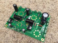
I should clear up any potential confusion with how I mounted my CCS ICs.
I wasn’t a huge fan of the usual method used for installing the ICs on the underside of the board, so I ended up swapping R13 with R19, and R23 with R29, allowing the ICs to be installed on the underside of the board but with a more conventional orientation.
I wasn’t a huge fan of the usual method used for installing the ICs on the underside of the board, so I ended up swapping R13 with R19, and R23 with R29, allowing the ICs to be installed on the underside of the board but with a more conventional orientation.
- Status
- This old topic is closed. If you want to reopen this topic, contact a moderator using the "Report Post" button.