I purchased an assembled SSE on an online auction site. I knew it had the led mod for the 12AT7. But once receiving the board, checked the SSE for correct parts, and found some differences. I contacted seller, he had no clue. Evidently an estate sale. I am wondering if the differences relate to the led mod. So before connecting power to the SSE I am looking for info/advice on what the changes will do.
Changes:
LEDs instead of C10,C20 & R10,R20?
R12,R16,R22,R26 220 ohm installed instead of 100 ohm?
R13,23 470 ohm installed instead of 330 ohm?
R2 220K ohm 2 Watt installed instead of 150K ohm 3 Watt?
R4 330K ohm 2 Watt installed instead of 150K ohm 2 Watt?
R3 22K ohm 2 Watt installed instead of 10k ohm 1 Watt?
R17,R27 500 ohm 5 Watt instead of default 560 ohm 5 Watt?
Last edited:
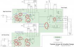
None of that makes any sense to me, either - but then again I'm not an EE. The good thing is that it doesn't look like anything was permanently altered, so it should be relatively simple to return it to "stock" condition if that's what you want. R17 and R27 are the output tube cathode resistors used to create bias. They probably differ from those shown in the schematic because a different tube was chosen per the chart on the Tubelab site (either that or the builder wanted a "hotter" operating point). R2 is the bleeder resistor for C1; the lower dissipation could be more problematic than the actual value depending on the current. R3/R4 create a voltage divider to elevate the tube heaters, but I'm uncertain about the significance of the change. Since their ratios are about the same, the difference in the elevated voltage shouldn't change much if at all.
Last edited:
"it looks like this board was never attached to any external parts; no wiring connected...an unfinished project"
That is what I thought too. but once receiving board and closely examining the solder pads the transformers had lightly and very cleanly tack on. I do not want to desolder the components for no reason and put it back to original design. So wanting learn more about the affects of these changed resistors and LEDs.
That is what I thought too. but once receiving board and closely examining the solder pads the transformers had lightly and very cleanly tack on. I do not want to desolder the components for no reason and put it back to original design. So wanting learn more about the affects of these changed resistors and LEDs.
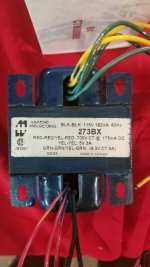
For more info I also was able to buy the power transformer for this SSE from same seller. So I will attach pic of specs if this helps. The seller also listed output EDCOR GXSE15-5K-8 that I did not win sold for more than new from edcor!
Attachments
"R17 and R27 are the output tube cathode resistors used to create bias. They probably differ from those shown in the schematic because a different tube was chosen per the chart on the Tubelab site (either that or the builder wanted a "hotter" operating point). R2 is the bleeder resistor for C1; the lower dissipation could be more problematic than the actual value depending on the current. R3/R4 create a voltage divider to elevate the tube heaters, but I'm uncertain about the significance of the change. Since their ratios are about the same, the difference in the elevated voltage shouldn't change much if at all."
Thanks Mr Zenith good feedback. The R2 bleeder issue had my attention too. But I do not understand exactly how lowering the current flow in the bleeder affects the circuit. The changed resistors around the 12AT7 and 10M45 I do not understand why and how this will affect the circuit.
Thanks Mr Zenith good feedback. The R2 bleeder issue had my attention too. But I do not understand exactly how lowering the current flow in the bleeder affects the circuit. The changed resistors around the 12AT7 and 10M45 I do not understand why and how this will affect the circuit.
Last edited:
"They probably differ from those shown in the schematic because a different tube was chosen per the chart on the Tubelab site (either that or the builder wanted a "hotter" operating point)"
MR Zenith, from looking at chart I speculate an EL34 at 400V, 5k Z output.
EL34 400 5000 387 34 510 66 24 4.86 7 0.4 4.39
MR Zenith, from looking at chart I speculate an EL34 at 400V, 5k Z output.
EL34 400 5000 387 34 510 66 24 4.86 7 0.4 4.39
That is an old board from before the legal issue that forced the name change to SSE.
None of these mods should prevent the board from operating. One of two things could be going on here.
1) The builder had many of these parts on hand and used what he had that was close in the places where it doesn't matter much. The power transformer is from 2003, before the SSE existed.
2) The builder purposely chose parts for a lower current and voltage operating point that most builders use. The power transformer is 700 VCT where most builders use 750 VCT. The B+ will be in the 400 volt range. This makes sense with the 500 ohm cathode resistors.
The other changes won't matter much except for the 470 ohm current set resistors for the CCS chips. This will result in about 5 mA of current through the 12AT7, which may be OK with the LED. I can't read any numbers off the CCS chips, they may be mosfets instead of IXYS chips. This was done mostly in Europe where IXYS chips were not available, but there were shortages of those part in the USA too early on. It's also possible that the builder intended to use something other than a 12AT7 tube.
I would go ahead and power it up. Check the plate voltage on the 12AT7 before installing output tubes. It should be around 200 volts.
"I can't read any numbers off the CCS chips"
The numbers are:
CP10M45S
IXYS K736
K0737M2
Thanks Mr Tubelab nothing like getting feedback from the designer in nearly real time! I have built several of your designs but always from stock. They all work and sound great. I saw this assembled and cheaper than parts to fill the board so I bid and won it!
With this being IXYS and I am going to use 12AT7 should I change to the 330 ohm precision resistor? Thank-YOU for sharing your passion with us all!!!
Attachments
Last edited:
"This will result in about 5 mA of current through the 12AT7, which may be OK with the LED."
"I would go ahead and power it up. Check the plate voltage on the 12AT7 before installing output tubes. It should be around 200 volts."
Took a few minutes for me to realize you already answered my question.
"I would go ahead and power it up. Check the plate voltage on the 12AT7 before installing output tubes. It should be around 200 volts."
Took a few minutes for me to realize you already answered my question.
There was a thread a few years ago, that petered out after big holes had been smacked in an SSE board, and directly heated tubes installed, making a DHT SSE.
The thread literally went all over the place, but part of it discussed how to get better performance from the SSE front end at lower B+ voltages, part of which meant lowering the current in the CCS; 470 ohms was about as low as you can go as best I recall. The victim board also had LED's installed in place of the cathode bypass/bias resistor.
Maybe the fellow that built this board had been following that thread, but did not install the DHT's, or maybe he wanted to use lower voltage tubes like 6V6.
Tubelab SE: Removing MOSFETs?
"The test board now has red LED's on the front end, in place of the resistor/bypass cap combination. I selected these on a trial and error basis. I took an arbitrary B+ voltage, measured the current at the cathode, then started swapping in LED's until I got a match. These nondescript red's turned out to be a good match. I changed the current set resistor in the CCS to 470 ohms"
"I'm using 25-30 year old red LED's for the 12AT7 bias on both boards. After reading up on this, I have no idea whether I went through the correct selection process. I didn't see any distortion difference between the LED and the RC combination; if anything, the LED might be slightly better. It sounds fine, so I guess I haven't botched anything. I'm wondering if a secondary artifact might be a visual indication of tube health and aging. "
Mr W5JAG I found these in posts 69 & 70 of your thread. Quite interesting reading.
How did you come up with the 470 ohm value?
So there is no real advantage of having the LED instead of the resistor and capacitor combo with a CCS?
... How did you come up with the 470 ohm value?
Trial and error, using different CCS set resistors and then measuring the resulting distortion ( IMD ), at the reduced B+ voltage in use in the test amp.
... So there is no real advantage of having the LED instead of the resistor and capacitor combo with a CCS?
They look neat, but, no, I could not measure or hear any difference. My test equipment is pretty mediocre, though. I think it is just a sideways move; others might have a different opinion or better data.
Both that DHT modified SSE and my daily driver SSE still have the LED's installed, for whatever that is worth.
"You really have to measure the current, don't you? The CCS will do whatever it takes to put the preset current into the tube. The max plate voltage specified for the 12AT7 is 300. It's cathode biased, so you would subtract that. It's not really voltage that kills the tubes, it's power.
Tubelab could better answer your questions, but here is all I know about the 12AT7 driver stage, fwiw:
With a generic chinese 12AT7, and the stock compenents in the CCS, at 300 volts, the current into the CCS was 16 ma.
When I jumpered the dropping resistor, it only took 260 volts to achieve 16 ma through the CCS.
In looking at my notes, I don't see where I actually measured the voltage at the plate. I would expect that to vary tube to tube because it wants to deliver a specific current, not voltage.
With a 1 Khz sine wave into the CCS at 1 v p-p, the output sine wave does not clean up until there is at least 230 volts into the CCS. That got 40 v p-p out.
At 250 vdc into the CCS, 1.8 v p-p in, yielded a maximum 70 v p-p out before clipping.
At 300 vdc into the CCS, 3.8 v p-p in, yielded a maximum 140 v p-p out before clipping.
At 350 vdc into the CCS, 4.0 v p-p in, yielded a maximum 190 v p-p out before clipping.
I didn't see the IMD change much as I varied the voltage, but the load made a difference - it was lower into a Hi-Z load, by quite a lot, than it was into a 600 ohm load."
Mr W5JAG Thanks for your info. I seen this from post 3 of the linked thread. I attempting to understand the CCS function in the SSE with both stock RC and LED mod. That datasheet if am reading correct the max current is 15ma, typical 10ma and 7ma been min. Mr Tubelab stated the I will have only 5ma with the way this SSE setup. Is that too low? Is 16ma too High? I have done the jumper R14,R24 10k 3W resistors when using lower voltage for low power tubes before in a stock SSE. I could not hear the difference in that setup. Though I still do so because I think it makes parameters more correct for the 12AT7 and CCS. I am intrigued by your experiments and cake pan builds.
Attachments
Last edited:
... I will have only 5ma with the way this SSE setup. Is that too low? Is 16ma too High? I have done the jumper R14,R24 10k 3W resistors when using lower voltage for low power tubes before in a stock SSE. I could not hear the difference in that setup ...
As current in the CCS decreases, distortion increases. Lower current would probably extend the 12AT7 tube life if that is a concern. Lower current is necessary as the B+ voltage decreases, for the reasons stated in the linked thread. I can't hear the distortion difference at lower current, but some people might. My mediocre test equipment has proven to me that I do not hear distortion unless it is pretty gross.
I think both of my SSE are running at 470 or maybe even 560 ohms in the CCS because they are both running with modest plate voltage; they are at a different house than I am, so I can't just go take a look.
You can try it at 5 ma with the LED's and then try it with more current with the traditional cathode resistor / bypass capacitor and see if you can hear any difference. You're not going to hurt anything if you can solder / desolder properly. Maybe just change one channel so you can hear them side by side.
- Status
- This old topic is closed. If you want to reopen this topic, contact a moderator using the "Report Post" button.
- Home
- More Vendors...
- Tubelab
- Some questions about mods made to SSE