I had a similar layout but put the toroid under the top plate, where you have your choke. Then you’d have more room for your OPTs, and maybe you could fit the motor run capacitor vertically.
Found some pics you posted of your build
https://www.diyaudio.com/forums/att...46d1579185771-sse-lacking-brightness-amp1-jpg
https://www.diyaudio.com/forums/att...45d1579185771-sse-lacking-brightness-amp4-jpg
Yes, very similar layout to what I was thinking. That gives me some confidence that what I am thinking for layout will be ok. Thanks for the post.
Found some pics you posted of your build
Yes, very similar layout to what I was thinking. That gives me some confidence that what I am thinking for layout will be ok. Thanks for the post.
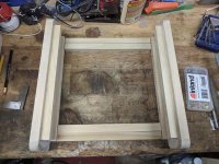
I had a tight squeeze because I managed to cut off too much when trimming the tray I used for the top plate. But the bit i am most happy with is that I have mains and HT on the left, as it is on the board, speakers and OPTs at the back, and signal on the right and front, so kept them seperate, and in the same places as the board connectors.
One more thing I’d like to do is add a triode/UL switch, instead of just UL.
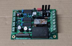
Question. In the thread for the soft start/switch board I am using Mark Johnson the designer mentions that he recommends for most amplifiers an inrush limiter (ex CL-60) between audio ground and chassis ground as a "ground lifter." I have seen this on a number of class A and class A/B amps but in looking through the SSE builds don't see any mention. Would this provide some benefit on the SSE?
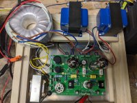
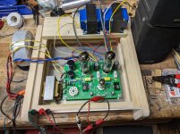
Got in some bench testing today. Good news is it makes music not smoke. Let it run for about 5 hours and it just played with no fuss. The one issue is it does hum through the speakers. Not loud enough to notice 10 feet away or when music is playing but audible when sitting a few feet from it with no music. Attached are the pics of the bench setup. Any ideas what I did to make it hum? Would like to figure out so I don't make the same mistake when I put it in the chassis proper.
Attachments
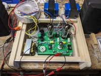
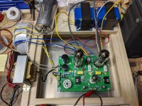
A little more experimenting tonight and some findings. I redid the grounding and changed to cathode feedback really just to get rid of the extra grounding point, pic attached. I also moved the power transformer and speakers to opposite sides as well as twisting some of the wires. When connected with the source turned off I still here a slight buzz. However when the source is on no buzz through the speakers with my ear right up next to them. But I do hear a buzz from the toroidal. I have it sitting on some rubber pads but it still buzzes. So it seems now I have the SSE sunning silent it's just the power supply. I'll do a general search for buzzing toroidals but any tips would be appreciated.
I should also add I removed the auxiliary capacitor in an effort to eliminate extra variables.
I should also add I removed the auxiliary capacitor in an effort to eliminate extra variables.
Attachments
Last edited:
Yet more experimentation and findings. First I found an old post by George (link) that talked about connecting the yellow and white wires of an Antek for the center tap and use the other white and yellow for the power input. That did not go well resulting in heat and crackling sounds. I will never revisit that again.
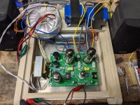
Next I focused on the 6.3v connections. On the Antek 2T350 there are 2 rated at 4A each. I had these connected in parallel in an effort to make sure I exceeded the 5A requirement listed for the SSE. When I disconnected these no transformer humming. I then tried hooking up just one pair, again no humming. I now had a hum free amp playing music. Pic attached is the hum free configuration.
Concerns and questions. First am I safe running the single 6.3v connection rated at 4A? I thought I read it was the KT88 that required 5A so if I stick with EL34s is 4A ok?
Question, if the single 6.3v 4A is safe could I modify the other 6.3V winding to supply the 5V rectifier? I originally planned to just use the solid state rectifier but have all parts on board for both.
Attachments
Web searches are telling me that a EL34 requires 1.5A for the heater and a KT88 requires 1.8A.
EL34 @ The Valve Museum
KT88 @ The Valve Museum
With one 4A winding I seem to be good with either tube even though with the KT88 I would not have much overhead. Why is the minimum spec for the SSE listed as 5A for the 6.3v winding?
EL34 @ The Valve Museum
KT88 @ The Valve Museum
With one 4A winding I seem to be good with either tube even though with the KT88 I would not have much overhead. Why is the minimum spec for the SSE listed as 5A for the 6.3v winding?
Found this post by Tom Christiansen with follow up from George talking about adding a 5v winding to a toroidal. Very handy. I have some 18g wire rated for 600v, would this be safe to use to add one 5V winding for the heater? What kind of dummy load would I use to test voltage if I don't want to hook up a 5AR4?
Turning a 6.3 V secondary into a 5 V secondary on an Antek 2T350
Turning a 6.3 V secondary into a 5 V secondary on an Antek 2T350
Last edited:
I went with the toroidal because it was readily available and inexpensive, purportedly does not run hot, and packaging options. I thought with the relatively low height I could mount it under the top plate but now with the soft start board taking up space that is less likely. I still think the lower profile with a cover over top will look good.
Working on the 5v winding now. Starting with 10 turns around the transformer, hooked it up to pin 2 and 8 of the 5AR4 tube and my volt meter. As with everything else I am testing I plugged it into a power strip, stood well back and hit the switch. 2.8v reading,so far so good. I'll report back on how many turns around it takes to hit 5v.
16 turns put the reading between 5 and 5.1v with everything hooked up. Listened to a few tunes and all seems good with the tube rectifier in circuit. Will be interesting to see what kind of B+ it runs with tube vs solid state. I do notice a reduction in volume with the tube. Project for another day.
Attachments
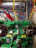
Well found a little more time tonight and attempted to measure B+ but since I am new to this not 100% confident in the points I measured. Please see attached photo, is this a valid way of measuring B+? I got 400v with the tube rectifier and 430v using solid state.
Attachments
Assuming my measurements of B+ are accurate I am thinking I should swap out the 680 ohm cathode resistor for a 560ohm resistor for solid state rectifier use and then switch in a 3300ohm resister in parallel for a total of ~480ohm for use with the tube rectifier. From the EL34 spec sheet 25watts is the max dissipation and based on the tubes and applications chart on the Tubelabs website this should put me close. Sound reasonable?
Found some checkout instructions by Ty_Bower
Simple SE checkout for dummies
These say to measure B+ between R4 and ground. Using this method today I get 422Vdc for solid state and 397Vdc for tube. I also changed out the cathode resistor for 560ohm. Again using those instructions I measured between R17 and ground and got 30.5Vdc solid state and 29Vdc tube. This equates to 21 and 19watts dissipation respectively. I then added a 3.3Kohm resistor to bring the cathode close to 480ohm and doing the same test got 24.25 and 21.55watts.
Does this seem correct? Reading the chart on Tubelab it says 400Vdc and 470ohm should put me at close to 25watts instead of the 21.44watts I am calculating.
Thanks vinylkid58. They are current production tubes. After switching between triode, UL, CFB modes last night I think I will leave it as is with the 560ohm resistor. The sound coming from my old garage speakers is as good as I have heard and being easy on the tubes sounds like a good idea. Also my bigger concern is that the toroidal buzzing is back. Happened when I put it back together after soldering in the new resistors. I really want to solve that before I put all the effort into finishing up the case.
Thanks mike567. Your post made me do some digging and I realized I made a basic mistake. The secondaries were wired parallel instead of in series for the center tap. Also going back to this post I understand my mistake. I knew what to do at some level but just did not put the pieces together. A basic error by me because I am new to all this.
The buzzing was much reduced after making this change but I still could hear a faint high pitched buzzing. I removed the 5V winding I added and it went away. Silent now.
Last piece to try in circuit before I disassemble and finish was a soft start board. I added that and it powered up but now the B+ voltage is 10V lower. I'll ask the question in the soft start thread and see if I have anything wrong.
- Home
- More Vendors...
- Tubelab
- Oh yeah another SSE build