I'd like to connect a small 12 volt dc fan inside my chassis to blow across the board (TSE). I realize the heater on the 5842s operate at 6.3 volts. Assuming my 12 volt fan will turn using 6.3 volts, where is the best place on the board to tap into the 6.3v circuit? Can I use pad F-6V?
These threads may be of some help.
Thanks! Very helpful. I searched before I posted but missed the second link you referenced. Exactly what I needed.
Can I use pad F-6V?
In all cases on the original TSE, the fan can be wired from F-6V to F-4V with the positive wire on the F-4V pad.
In the case of a 300B implementation the F-6V pad is jumpered to ground, so the fan can be connected from F-4V to ground, or directly across C1, whichever is most convenient.
These pads were actually intended as inputs for the few people who used this board as a driver for something bigger like an 845 or 833A.
The electrical connections in the new TSE-II are the same, but the pads are no longer present since virtually nobody except me used them. The negative fan wire goes to ground in the 300B version, or the negative end of C2 in the 45 / 2A3 version. The positive fan wire goes to the positive end of C1.
Depending on the line voltage, power transformer and tube lineup the voltage here will be between 6 and 8 volts.
Many small fans intended for 12 volt operation work fine at a lower and quieter speed on this voltage. Fans intended for 5 volt or USB operation (laptop coolers) don't like this much voltage and a resistor in series with the fan should be used to slow them down for quiet operation.
In all cases on the original TSE, the fan can be wired from F-6V to F-4V with the positive wire on the F-4V pad.
Perfect. Thanks, George. This would be easier than adding another rectifier / cap. I'm going to try to use a small (40mm) 12v fan, just to get a little circulation inside the chassis.
Looking at the top plate of your amp on other thread, it may help to drill some vent holes at two locations I circled in green if still feasible. Even better if there are holes at the bottom plate as well. Those two locations do generate a lot of heat besides the tubes.
Attachments
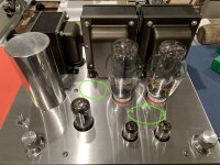
Looking at the top plate of your amp on other thread, it may help to drill some vent holes at two locations I circled in green if still feasible.
Thanks. I have contemplated that. I may end up doing it at some point. For now, I've talked myself of it for a few reasons.
1) It's major surgery. I'd have to desolder, disassemble, etc., and then risk something going wrong on the CNC (then having to start over!).
2) The top plate is 3/16" thick and it does get very warm. So it's acting as a heatsink to some degree.
3) The underside is perforated (60% open, if I recall) so air is definitely able to come up through the bottom and vent around the tube openings (albeit not optimally - hoping the fan will help that). And,
4) I'm still relying on the smallish board-mounted sinks at the MOSFETs. I am contemplating adding a piece of aluminum bar with some relief cuts to the fet heatsinks - in between the two sinks essentially bolting them together back to back. That should help with heat dissipation a bit.
The sink at D1 and U1 is BIG, so I have less of a concern there.
My plan to add the fan is more preventive now that I have the amp semi-apart for the fet replacement.
By the way, I hope you're well. Our mutual friend tells me you're working on a project near him. Next time you're out this way, drop me a line. Would be great to catch up!
I'm still relying on the smallish board-mounted sinks at the MOSFETs. I am contemplating adding a piece of aluminum bar
I don't see why one couldn't apply the resistor / Zener circuit from the TSE-II in an original TSE to reduce the mosfet heat. I have a board sitting unused on my desk, maybe I can try it.
- Status
- This old topic is closed. If you want to reopen this topic, contact a moderator using the "Report Post" button.
- Home
- More Vendors...
- Tubelab
- Chassis fan connection on TSE?