I am guessing that the regulars around here, maybe even George himself, have become a bit bored with these SSE builds. I mean really, how many years has it been?
On the other hand, for people like me this is new and exciting - and I have really enjoyed reading other people's build threads. So I figured I would post my journey.
So far, I have obtained the board and sourced all the minor components, built the board, and have some of the major components - with the rest on the way.
This is what I've decided:
- "Inverted" orientation for under-chassis mounting
- Current inrush limiter on mains primary
- Hammond 274BX
- C1 = Nichicon 47uF 500v
- C2 = Kemet 150uF 500v
- Triad C14X choke
- Kemet 80uF 470vac PP motor run cap
- TR1, D3 and D4 installed
- Binding posts installed for C11/21 and R17/27 to enable easy replacement
- CDE 942 series PP coupling caps C11/21
- 680ohm to start off R17/27 (plan to run EL34 exclusively for quite some time)
- a selection of various other values for R17/27 for future use
- Gold-plated copper inputs and speaker terminals
- 18GA 600v 200C tinned copper silicone hookup wire
- probably DIY chassis - typical wood frame and aluminum top
- not 100% decided on OPTs yet - have some cheap Chinese ones on the way just for testing
- Tubes will be EH EL34, NOS GE 12AT7, and various rectifiers (Shuguang 5AR4, NOS RCA and Sylvania 5U4GB).
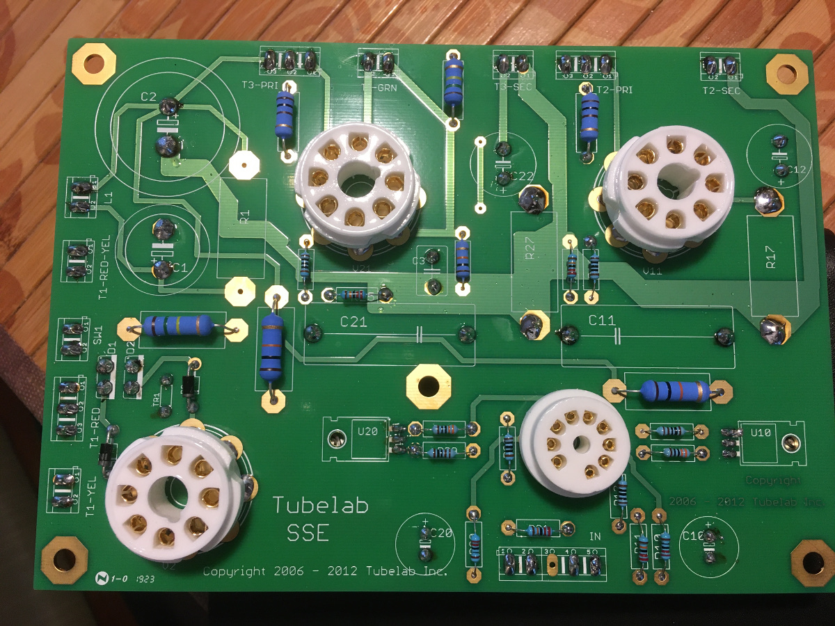
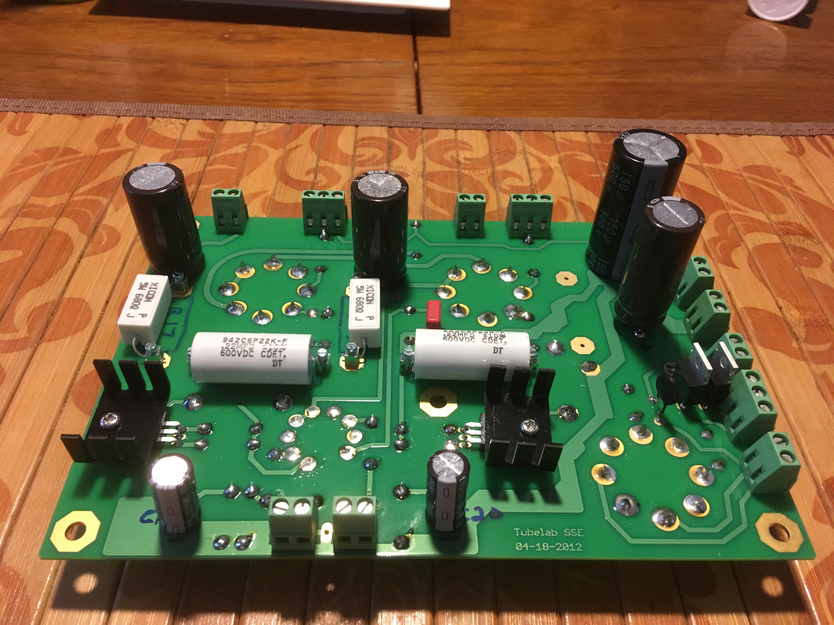
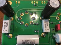
Photos of progress so far:
(Note: the way I have oriented the C11/21 and R17/27 binding posts may seem odd, but they make component installation/replacement easier (for me, anyway).

On the other hand, for people like me this is new and exciting - and I have really enjoyed reading other people's build threads. So I figured I would post my journey.
So far, I have obtained the board and sourced all the minor components, built the board, and have some of the major components - with the rest on the way.
This is what I've decided:
- "Inverted" orientation for under-chassis mounting
- Current inrush limiter on mains primary
- Hammond 274BX
- C1 = Nichicon 47uF 500v
- C2 = Kemet 150uF 500v
- Triad C14X choke
- Kemet 80uF 470vac PP motor run cap
- TR1, D3 and D4 installed
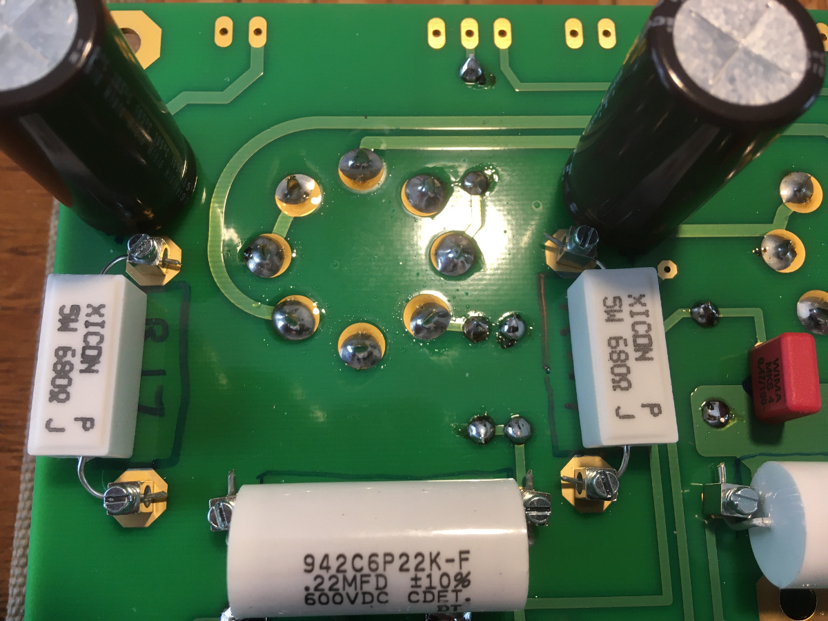
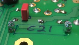
- Binding posts installed for C11/21 and R17/27 to enable easy replacement
- CDE 942 series PP coupling caps C11/21
- 680ohm to start off R17/27 (plan to run EL34 exclusively for quite some time)
- a selection of various other values for R17/27 for future use
- Gold-plated copper inputs and speaker terminals
- 18GA 600v 200C tinned copper silicone hookup wire
- probably DIY chassis - typical wood frame and aluminum top
- not 100% decided on OPTs yet - have some cheap Chinese ones on the way just for testing
- Tubes will be EH EL34, NOS GE 12AT7, and various rectifiers (Shuguang 5AR4, NOS RCA and Sylvania 5U4GB).
Photos of progress so far:
(Note: the way I have oriented the C11/21 and R17/27 binding posts may seem odd, but they make component installation/replacement easier (for me, anyway).
Attachments


Last edited:
I am guessing that the regulars around here, maybe even George himself, have become a bit bored with these SSE builds. I mean really, how many years has it been?
On the other hand, for people like me this is new and exciting - and I have really enjoyed reading other people's build threads. So I figured I would post my journey.
So far, I have obtained the board and sourced all the minor components, built the board, and have some of the major components - with the rest on the way.
This is what I've decided:
- "Inverted" orientation for under-chassis mounting
- Current inrush limiter on mains primary
- Hammond 274BX
- C1 = Nichicon 47uF 500v
- C2 = Kemet 150uF 500v
- Triad C14X choke
- Kemet 80uF 470vac PP motor run cap
- TR1, D3 and D4 installed
- Binding posts installed for C11/21 and R17/27 to enable easy replacement
- CDE 942 series PP coupling caps C11/21
- 680ohm to start off R17/27 (plan to run EL34 exclusively for quite some time)
- a selection of various other values for R17/27 for future use
- Gold-plated copper inputs and speaker terminals
- 18GA 600v 200C tinned copper silicone hookup wire
- probably DIY chassis - typical wood frame and aluminum top
- not 100% decided on OPTs yet - have some cheap Chinese ones on the way just for testing
- Tubes will be EH EL34, NOS GE 12AT7, and various rectifiers (Shuguang 5AR4, NOS RCA and Sylvania 5U4GB).
Photos of progress so far:
(Note: the way I have oriented the C11/21 and R17/27 binding posts may seem odd, but they make component installation/replacement easier (for me, anyway).
Looks good so far, I like the idea of the binding posts, where did you get those by chance? Might try to install them on mine.
These look about right?
8737 Keystone Electronics | Connectors, Interconnects | DigiKey
Keep us posted! I wonder how many of these things this board has seen built

Last edited:
Looks good so far, I like the idea of the binding posts, where did you get those by chance? Might try to install them on mine.
These look about right?
8737 Keystone Electronics | Connectors, Interconnects | DigiKey
Keep us posted! I wonder how many of these things this board has seen built
Hey thanks!
The binding posts I used are very close to those. Same manufacturer, but part number 8730. I have no idea what the difference is (if any). I ordered from Mouser 8730 Keystone Electronics | Mouser Canada
The only thing to keep in mind is to be very gentle with the torque. Set the screws just firmly enough to bind the leads - a bit too much torque and that pin is going to spin and crack the solder joint (a smart engineer would have designed them with non-round pins).
Last edited:
... - a bit too much torque and that pin is going to spin and crack the solder joint ...
Just an FYI regarding those binding posts ... some of the pads are plated through, and I think that includes some of the coupling cap pads, and maybe the cathode resistor(s), making a connection between the top and bottom of the boards. If that connection is broken or otherwise not made, the board won't work and then you have to reestablish the connection with the component lead.
I don't know if that is applicable to these binding posts, again, just something to keep in mind.
Very good to know, and all the more reason to exert as little torque as is necessary to bind the leads. Thank you.
You ever come across this thread or something similar? Seems like a good idea to install a switch for tube rolling/trying different tubes. I might give it a shot myself.
Simple SE Cathode Resistor Values
Simple SE Cathode Resistor Values
You ever come across this thread or something similar? Seems like a good idea to install a switch for tube rolling/trying different tubes. I might give it a shot myself.
Simple SE Cathode Resistor Values
Yes, I actually read all about that on Russ's ( rknize ) blog - Tubelab Simple SE – Construction – metaruss
I decided against doing it, to avoid complexity. I might add it later, but I doubt it. Having the binding posts will allow me to swap resistors very easily when I want to swap tubes. My plan is to get the amp up and running with EL34 and do the check out. Once I am happy with the bias point and the rest of the voltage and dissipation, I am going to stick the Russian 6P3S-E tubes in and see if they need a different resistor value or not.
Basically I am going to gather all the data I need for these two types of tubes and then decide if I am OK doing resistor swaps or if installing a switch is the way to go. I suspect that I will like the sound of one type of tubes over the other and not do much tube rolling after that. Or if I do switch, it will be every few months or so and I won't mind swapping resistors.
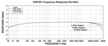
The Hammond 274BX arrived yesterday. The Chinese OPTs have not even left the wharehouse (due to Corona, I suppose). I think I am going to go ahead and order the Hammond 125FSE (4.5 pound, 20 watt) OPTs. Here is the frequency response at rated output power (20w). I figure at 6 watts or so they will be flat (+/- 1dB) to 30Hz (at least) which is more than I need.
Attachments
Last edited:
I finally made the decision and pulled the trigger on a pair of Transcendar TT-338-OT. They are expensive, but as they say "you only live once", and "you can't take your money with you."
I have some ideas for a cheap but cheerful chassis. I think I'll start gathering up the pieces this weekend. It may be another month or so (at least) before I am close to powering the amp up, although I do have the cheap Chinese OPTs on the way I could use for testing if everything else is ready.
I have some ideas for a cheap but cheerful chassis. I think I'll start gathering up the pieces this weekend. It may be another month or so (at least) before I am close to powering the amp up, although I do have the cheap Chinese OPTs on the way I could use for testing if everything else is ready.
Last edited:
Good choice cogitech, and look forward to build updates.
They sure look very cool, the specs are too!
Congrats with your'e choice cogitech.
Looking forward to see your'e build proceed
Jesper.
Btw. : what kind of chassis are you considering to build (alu' / wooden ? Both ?)
Thanks guys.
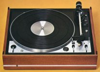
Jesper, my plan is to construct a typical wood base / aluminum top chassis. I have some very high density, multi-ply wood (like baltic birch) that I might use, however what I would really like to do is use teak wood. I would love it to have a classic early 70s look similar to the Dual 1229 turn table (seems to me a Dane was involved in this design
):Attachments
Last edited:
Well I don't think I'll be doing the chassis in teak wood. I checked out prices at the local lumber store and I was a bit shocked. A solid chunk was going to cost ~$200 and it was far thicker than I needed. They also have 3/8" teak ply but it was $85 for 3'x3' sheet.
I might see if there is a piece of teak furniture on the local buy&sell website for a reasonable price, but I suspect I'll end up using plywood I have in the garage. I've got 2 different thicknesses of Baltic Birch and I can stain it to match my speakers.
For the top, I bought a Paderno 14" x 16" uncoated 2mm aluminum cookie slide:

It was on sale for $24. I'll use it upside down so the rolled edges are at the sides. They will make lifting/moving the amp easier. 14" x 16" is quite large, but I agree with Morgan Jones that it is much better to have too much space in/on the chassis than barely enough.
I also completed the top layout and began drilling. I have incorporated most of Jones' design principles into the layout, however I have so much real estate on the top that I was able to make it aesthetically pleasing (I think) rather than purely practical. A centre punch and some step drill bits (also on sale) made fairly easy work of it. I am happy to say that the tube sockets and brass stand-offs all lined up adequately on the test fit.
I have also decided to add the following to this amp:
- 2 front-mounted, back-lit, analog VU meters (pure eye candy)
- 1 top-mounted, 0-500v, analog voltmeter to monitor B+
- 2 top-mounted, 0-100ma, analog ammeters to monitor power tube plate currents
This will delay the project by at least another month as I wait for the parts (China).
I might see if there is a piece of teak furniture on the local buy&sell website for a reasonable price, but I suspect I'll end up using plywood I have in the garage. I've got 2 different thicknesses of Baltic Birch and I can stain it to match my speakers.
For the top, I bought a Paderno 14" x 16" uncoated 2mm aluminum cookie slide:
It was on sale for $24. I'll use it upside down so the rolled edges are at the sides. They will make lifting/moving the amp easier. 14" x 16" is quite large, but I agree with Morgan Jones that it is much better to have too much space in/on the chassis than barely enough.
I also completed the top layout and began drilling. I have incorporated most of Jones' design principles into the layout, however I have so much real estate on the top that I was able to make it aesthetically pleasing (I think) rather than purely practical. A centre punch and some step drill bits (also on sale) made fairly easy work of it. I am happy to say that the tube sockets and brass stand-offs all lined up adequately on the test fit.
I have also decided to add the following to this amp:
- 2 front-mounted, back-lit, analog VU meters (pure eye candy)
- 1 top-mounted, 0-500v, analog voltmeter to monitor B+
- 2 top-mounted, 0-100ma, analog ammeters to monitor power tube plate currents
This will delay the project by at least another month as I wait for the parts (China).
Cool cogitech, great plan you have...
I think that the voltmeters you ordred could be like mine ?
They are fairly easy to hack to get light in, well not 100% perfect but good enough for me through
Jesper.
Yes, they appear to be exactly the same. I may pick your brain in the future about how you added the lights.
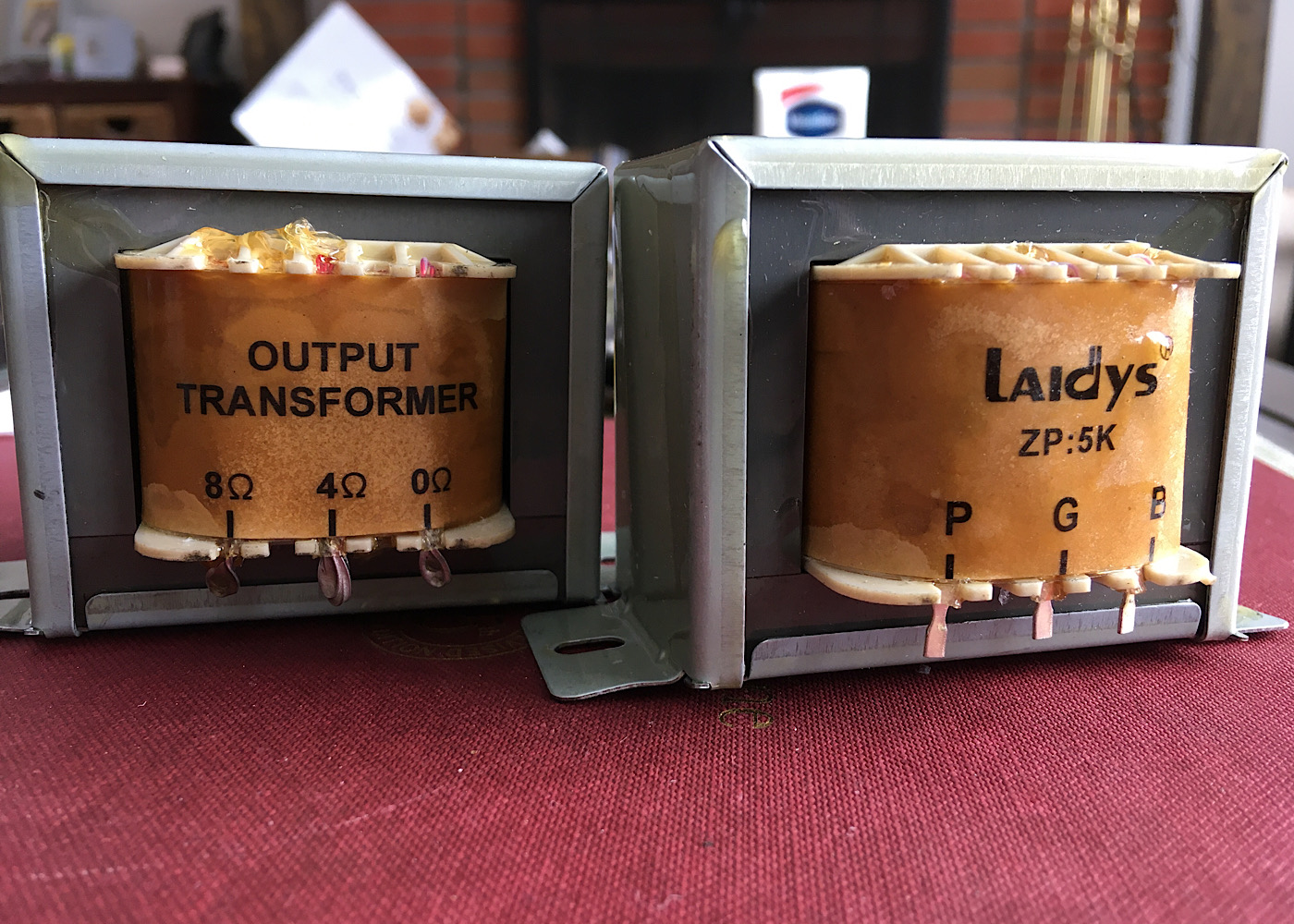
I'm happy to report that the Chinese Cheepies have arrived.
- They have a U/L tap (nice surprise!)
- They weigh 996g and 991g respectively (~2.2 lbs)
- Primary resistance is 370ohms (both the same)
- Secondary resistance between 0 and 8ohm is 1.8ohms (both the same)
- I have no way to test inductance but the claim is 25Hy, which seems entirely appropriate for this size of OPT
- I'm calling it a 6 watt OPT
Note: they are the same size, despite the perspective distortion in the photo:
I now have nothing stopping me from hooking everything up an testing, but I think I'd rather get the chassis put together (rough-in anyway) first.
Looking like a really nice build so far, Probably a good idea to have a "testing" set of output transformers, I've wondered about them myself for some time.
Looking like a really nice build so far, Probably a good idea to have a "testing" set of output transformers, I've wondered about them myself for some time.
To be perfectly honest, I plan to compare them to the Transcendars and if I can't tell much of a difference at the SPLs that I need/want I might just sell the Transcendars and recover most of my money. I do really wonder how much difference I will be able to hear at 1-3 watts of output power, or even 6-7 for that matter. By April I should know the answer to that.
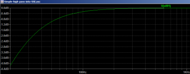
Been thinking a lot about frequency response (due to another discussion on OPTs) and I have decided to add a switchable high-pass filter on my SSE just for schlitz n' giggles. It'll look something like this:
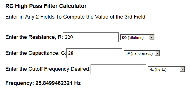

I already have a bunch of 10nF film caps so I will just parrallel 3 of them and install in series (switchable) with each input channel.
It'll drop 1.4dB at 40Hz and continue to drop from there. My speakers roll themselves off pretty hard right around 40Hz (F10 ~35Hz) so maybe gradually relieving the OPTs and transducers from the sub-40Hz signal will be a good thing. Why drive that energy through those components if I'm not going to hear it anyway and it is possibly/probably going to cause saturation and/or inter-modulation distortion at higher SPLs? Room modes tend to give me loads of low bass gain, anyway.
The switch will probably get switched back and forth a few dozen times in the first week and then stay in one position for years, but what the heck. Cheap thrills.
Attachments
Last edited:
- Status
- This old topic is closed. If you want to reopen this topic, contact a moderator using the "Report Post" button.
- Home
- More Vendors...
- Tubelab
- Yet Another SSE Build Thread