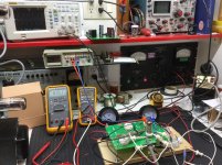
I’ve got a SSE on the bench for checkout. At this point I’m only operating with the 12AT7 installed and I’m operating it off a regulated power supply connected at the choke terminal. As such, I’m taking some measurements around the CCS and driver tube OPs at various B+ values. I’ve run up against something interesting and wondered if it’s been discussed previously.
First, I’m guessing that R14/24 is there to dissapate some heat and take some of the load off the CCS heat sink. Is that correct George? It wouldn’t have occurred to me to use that resistor in the design and I’m wondering it’s purpose.
To the point now, I’m noticing that the AC wave form observed at the plate looks pretty horrible until the B+ voltage is dialed up to about 375 volts. Then it begins to look terrific. That’s not a problem for most users obviously, since a higher B+ is typical, however it is a curiosity to me.
I placed a DMM across R14/24 and observed that voltage drop across that resistor was about 86 volts and constant with B+ from 500 volts down to, you guessed it, 375 volts - after which the voltage drop (and current) begins to decline. With lower B+ the CCS appears to fail to control current as it looses its required driving force. I’m thinking R14/24 then starts acting like a load resistor and suddenly the 12AT7 begins to operate across diagonal load lines rather than the horizontal load lines of a CCS load; hense the ugly wave form.
Assuming for a quick moment that I’ve got my head around this correctly, and that might be a stretch, one might want to reduce the value of that resistor if one planned to operate at a B+ value much below 400.
What say those who know?
take some of the load off the CCS heat sink. Is that correct George?
Yes.
one might want to reduce the value of that resistor if one planned to operate at a B+ value much below 400.
Also correct. I have stated this somewhere, as well.
My 6V6 SSE runs on about 325 volts, and those resistors have been replaced with a piece of wire.
The results are somewhat tube dependent, but I have seen SSE's work fine on 360 volts of B+ with the resistors in place, but it depends on what the plate voltage is on your 12AT7 with 10 mA through it.
Some new production "12AT7's" don't bear much similarity to the NOS 12AT7's that I used during design and testing of the SSE....which happened almost 15 years ago. I know that some JJ's look more like 6DJ8's than 12AT7's and I have not looked at any new production tubes in a long time.
I see. Determine voltage surplus to the circuits needs and dissapate that through a resistor. Thanks for the insight. I did try clipping in another 10k in series and got down to 330. Two got me to 315. A shorted resistor down to 285. Good stuff.
I bought a sleeve of new RCAs decades ago and I’m using one of those. I’ve also got some Sylvanias I’ll try as well and see if there are any differences. I don’t think I have any new ones to compare.
I intend to monkey around with the 10m45 control resistors to get the current up to 10ma. The 330R doesn’t quite make it to 9 with these.
Attachments
Last edited:
Yes, this thread meanders all over the place, but it was discussed in some depth somewhere in it:
Tubelab SE: Removing MOSFETs?
12BH7 will work at considerably lower voltages than 12AT7, but it is an imperfect solution as the overall gain is reduced by a substantial amount.
Tubelab SE: Removing MOSFETs?
12BH7 will work at considerably lower voltages than 12AT7, but it is an imperfect solution as the overall gain is reduced by a substantial amount.
8 to 10 mA is Ok, and didn't make much difference in sound or distortion measurement unless the 10M45 gets close to running out of headroom. If your B+ is kinda low a bit more tube current might be good. Too much current gets the plate voltage down into the distortion zone though.
12BH7 will work at considerably lower voltages than 12AT7, but it is an imperfect solution as the overall gain is reduced by a substantial amount.
Thanks, I’ll look through that thread.
I have a couple of surplus PTs that should work just fine with approx 400 vdc B+ so I don’t really have a problem to solve, but I was quite intrigued by what I saw on the scope. I’ve used the 10m45 before but without the resistor and had not observed this before. It was unexpected how suddenly and dramatically the wave form changes when the CCS kicks in. With the scope one can easily see why the 12AT7 has something of a poor reputation as an audio tube and how the CCS utterly transforms its performance.
- Status
- This old topic is closed. If you want to reopen this topic, contact a moderator using the "Report Post" button.