In the TSE II it ishttp://www.tubelab.com/images/AssemblyManualTubelabSE/TSE_board.jpgs in the bias supply circuit located after C7
Its no longer used in TSE II
After a 14 year run, the TSE must DIE!
Look at Post #1
B.O.M.
It states no longer used.
Whatever has been published by George regarding the TSE II is in these pdf's.
After a 14 year run, the TSE must DIE!
Look at Post #1
B.O.M.
It states no longer used.
Whatever has been published by George regarding the TSE II is in these pdf's.
Hi Andrewbee- Yes, I know that...
My question is- has R7 been replaced by R6 on the TSE-II board. The new board that Tubelab hasn't had time to post a schematic.
I am trying to do the checkout of the new board I finished populating with all the components.
According to the old schematic (TSE) and checkout procedure on the Tubelab website, you can check the B- voltage by applying test leads between R7.
It looks like R7 has been replaced by R6 on the TSE-II board I have.
Nobody has built the new TSE-II amp can verify this?
I am trying to do the checkout of the new board I finished populating with all the components.
According to the old schematic (TSE) and checkout procedure on the Tubelab website, you can check the B- voltage by applying test leads between R7.
It looks like R7 has been replaced by R6 on the TSE-II board I have.
Now I understand you. You want to measure the Bias supply voltage.
R7 on the old board (TSE) looks like it was simply there to discharge the bias supply quickly on power down.
On the new board (TSE II) where there is no R7 you can measure anywhere from R6 on the C7 side to the junction with R24 / R25 on one channel or R13 / R14 on the other channel. You only need to measure 1 channel since they use the same bias supply.
Look at the TSE schematic and compare it with the TSE II schematic they are the same really.
Remember you are measuring a - voltage so place your probes accordingly.
I think my TSE II ended up with ~ -200Vdc iirc
Remember the R36 / D6 values / wattage when running over 350 Vdc B+
I run my R36 off board and on the chassis (I use a 50W Aluminum W.W. resistor).
No, that is signal ground, not power ground.
Look here After a 14 year run, the TSE must DIE! at post #245, there are other pictures from George. Its a bit long but read the whole thread slowly, there is just about all the information you need, its just spread out across the dozens of pages.
I made some notes you can take a look at and hopefully they will help you.
The pages with the Black background are the checkout, leave them for last.
Read the other pages (the pages with the White background) first - several times. Along with the pictures in the link above it should help as you now have a visual reference to the text.
Its' easier to make it right the first time rather than finding and correcting errors.
Last edited:
I forgot to upload the files in last post. Hopefully I got it right this time!
This is all postings from George, I just made it Cliff notes style.
This is all postings from George, I just made it Cliff notes style.
Attachments
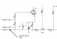
Here's what is still causing me to be confused:
The white wire shown in the TSE checkout (TSE, not TSE-II), is supposed to be connected to the outlet plug ground. That is, black and white wire from the plug to the transformer, then green (ground) wire to the white clip on lead shown in the photo.
What is the white clip on lead connected to?
Is it though the center tap of the power transformer?
Thanks!
Attachments

Last edited:
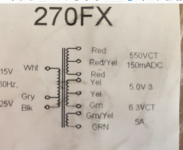
Got me a Hammond 270FX power transformer for use on a TSE-II board.
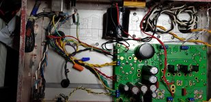
I'm trying to do an initial checkout of the new board, the new board isn't mounted in the chassis yet.
Does anybody know where the ground wire is connected to the TSE-II board for checkout?
The TSE has a photo of a white wire connected from the power input ground wire to the TSE board. Is the sound wire connected to the gray wire on the input side of the transformer, then a ground wire to the board for checkout is not required?
Attachments
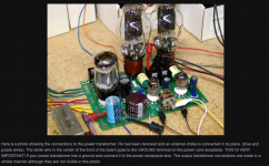
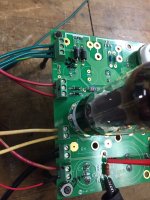
Look at the attached picture of my TSE II. For full disclosure my lead dressing is worse than poor. I have an exposed CL90 and exposed contacts on my I.E.C.connector. in my defense I got it to working stage but have never actually cleaned up the wiring ....yet. One of these days. I have a bottom cover so the only person whose digits should be near the insides are mine and if I injure myself .....well I know better. Now that's out of the way.
Do not get hung up on the wire colours in the TSE picture. There is no color code in use there. George tells you what they are used for e.g the White wire IS his ground wire. He is just using wires with Alligator clips to test with so the colours don't matter. All that matters is YOU know which wires should go where.
Look at the attached picture. See that "U" shaped wire about midway and above the Black cylindrical capacitor (Solen). Thats my "Ground Buss".
I have five wires connected to it, 2 are Black and thinner gauge then a Green with yellow Stripe, red with Yellow Stripe and another Green with Yellow Stripe.
The Two Black wires are from my speaker negative terminals. The two Green with Yellow Stripes are as follows, one is the Ground point of the I.E.C. connector (the ground from your AC power cord) and the other is from the chassis. The Red with Yellow stripe is the Power Transformer secondaries High Voltage Centre tap, same as the picture you attached.
These are all safety grounds, do not leave them out (except the Red with Yellow stripe which is not safety related but needs to be here).
The signal grounds are the inside contacts of the Blue connectors about midway up on the Left side of the picture. I think its both inner contacts on each of the Blue connectors but read the notes I posted, it mentions it.
Do NOT make any connection between the signal and power grounds. Nothing will blow up or anything but you will most likely create a ground loop and get lots of HUMMMMMM.
BTW, I used the connectors on the board to attach wires so I can remove the board if I want / need too easily. You don't have to use them as you can always simply solder them (wires) to the board.
Attachments
Last edited:
The clip leads in the photo are my audio inputs. They were clipped to the leads coming from the audio generator I used for testing, then they were clipped to the RCA cables for playing music. White and yellow are audio input hot, and both blacks are audio input cold (audio ground).
The white wire soldered to the front of the PC board near C5 is the wire that goes to the line cord socket ground.
The new board is slightly different since there is no volume pot. There are places for a 3 terminal strip for each channel input, much like the SSE. The pair of holes closest to R20 (pot) are all signal ground. Only one needs to be connected, the extras are to support my volume pot board when testing. The leftmost L-input terminal is L audio hot, and the right most R-input terminal is R audio input hot. Run only the signal inputs and their shield (ground to this area).
The main board ground is the T1-RED-YEL connector. One of these terminals is used for the HV secondary CT. It is usually a red wire with a yellow stripe (except on an Edcor transformer). The other is used for the ground connection to the power input, and any other power related grounds. Some users mount a ground lug on the chassis, and run a short wire from the lug to this board terminal, then tie all other grounds (except inputs) to this lug. Ditto the AUX cap if you use one.
The T1-RED connector is used for the HV secondary winding on the power transformer (usually red wires). Connect one red wire to each outer terminal. Make NO connection to the center terminal.
The 6.3 volt heater winding on the transformer goes to the T1-GRN connector. The green wires go to the two terminals closest to the rear edge of the board. The CT (usually green with a yellow stripe) goes to the terminal closest to the front edge of the board. Make NO other connections to these terminals. Do not ground any wire from the 5 or 6.3 volt windings....bad stuff could happen if you do.
There MUST be NO connection made from the primary side of the power transformer to ANYTHING related to the board, the inputs or the speaker wiring. The black, white and grey wires are connected to your house power and you don't want that connected to anything related to the amps circuitry.
The ONLY connection from the power input should be the safety ground, which MUST be connected to the chassis and board ground.
The power transformer you have has an extra tap on the primary for today's high line voltages. The white and black wires are the power input and go to the fuse, power switch, and power input connector. Make NO connection to the grey wire. Tape it up so it can't touch anything. Make NO connection from the primary side wiring to ground or anything related to the board circuitry.
The white wire soldered to the front of the PC board near C5 is the wire that goes to the line cord socket ground.
The new board is slightly different since there is no volume pot. There are places for a 3 terminal strip for each channel input, much like the SSE. The pair of holes closest to R20 (pot) are all signal ground. Only one needs to be connected, the extras are to support my volume pot board when testing. The leftmost L-input terminal is L audio hot, and the right most R-input terminal is R audio input hot. Run only the signal inputs and their shield (ground to this area).
The main board ground is the T1-RED-YEL connector. One of these terminals is used for the HV secondary CT. It is usually a red wire with a yellow stripe (except on an Edcor transformer). The other is used for the ground connection to the power input, and any other power related grounds. Some users mount a ground lug on the chassis, and run a short wire from the lug to this board terminal, then tie all other grounds (except inputs) to this lug. Ditto the AUX cap if you use one.
The T1-RED connector is used for the HV secondary winding on the power transformer (usually red wires). Connect one red wire to each outer terminal. Make NO connection to the center terminal.
The 6.3 volt heater winding on the transformer goes to the T1-GRN connector. The green wires go to the two terminals closest to the rear edge of the board. The CT (usually green with a yellow stripe) goes to the terminal closest to the front edge of the board. Make NO other connections to these terminals. Do not ground any wire from the 5 or 6.3 volt windings....bad stuff could happen if you do.
Is the sound wire connected to the gray wire on the input side of the transformer, then a ground wire to the board for checkout is not required?
There MUST be NO connection made from the primary side of the power transformer to ANYTHING related to the board, the inputs or the speaker wiring. The black, white and grey wires are connected to your house power and you don't want that connected to anything related to the amps circuitry.
The ONLY connection from the power input should be the safety ground, which MUST be connected to the chassis and board ground.
The power transformer you have has an extra tap on the primary for today's high line voltages. The white and black wires are the power input and go to the fuse, power switch, and power input connector. Make NO connection to the grey wire. Tape it up so it can't touch anything. Make NO connection from the primary side wiring to ground or anything related to the board circuitry.
This is a very nice thread ")
Information collected in one thread for the checkout & connections.
There is something through i have to ask! In the one-electron UBT3 OPT datasheet they suggest a fuse rated twice the expected operation current (say 150-200mA for 300b) connected at the b+ primary side of the OPT, for protektion of the windings etc... if a bias/tube etc. error occours.
Lots of people would properly claim that they dont want any fuses in audiopath, but if it protects the circuit it maybe is a good idea at least until everything is running and tested.
Another thing i would like to know, is about the input (audio in) connections.
Do we prefer twisted pair without screen? Or do we prefer coax with one wire with screen connected in both ends, or anything else?
Would be nice to have this information also here
Have a good day.
Jesper.
There is something through i have to ask! In the one-electron UBT3 OPT datasheet they suggest a fuse rated twice the expected operation current (say 150-200mA for 300b) connected at the b+ primary side of the OPT, for protektion of the windings etc... if a bias/tube etc. error occours.
I personally have never fused an OPT. Its is a good practice from a safety point of view however. I tend to over engineer things so am not too worried but if there was an issue then a fuse could save you an OPT, Tubes, maybe your house.
Another thing i would like to know, is about the input (audio in) connections.
Do we prefer twisted pair without screen? Or do we prefer coax with one wire with screen connected in both ends, or anything else?
Use what you have. I use a shielded cable that I get from a cannibalized computer video cable and ground the shield. I don't see why simple twisted pairs will not work, I have used Cat 5 twisted pairs for years and when the shielded cable I use now is finished will use Cat 5 again unless I get more shielded cable.
In other words, its the same amount of work or effort to use a shielded Cale as it is twisted pair so if you have the shielded cable use it, technically the shielded cable will be better but unless you have a noise issue using twisted pair that you do not have with the shielded cable then its just semantics.
Just try to keep the input wires short and away from noise sources and it will be fine. Coax works but its stiff and thick so I don't use it for those reasons.
I rather a flexible cable.
Duke's TSE-II Checkout
Today, I successfully completed the checkout of a TSE-II board, copyright Tubelab, 2019.
The primary transformer wires are connected from the outlet plug black and white wires to transformer black and white wires. The green (ground) wire from the outlet plug is connected to the board ground nearest the front of the board next to C5, last connector, marked T1 RED_YEL on the board.
Without a rectifier tube installed, the power receptacle was plugged into the Variac and the power was turned up slowly while watching for fireworks/smoke. Filament voltage between pins 2 and 8 measured 5.3 Vac. B+ voltage across R30 measured -0.363 Vdc. B- voltage across R6 measures -145.3 Vdc. Again, these measurements are without the rectifier tube installed in the board.
Next, a 5AR4 rectifier tube was installed and allowed to warm up. B+ voltage measured 372.3 Vdc. B- measured -143.2 Vdc.
I'm using 45 tubes. Filament voltage across pins 1 and 4 measured ~2.476 Vdc on both tube sockets.
The gate voltages for the output tubes measured about -107 Vdc.
The driver and output tubes are not here, so I'll have to continue tomorrow.
Attachments
Inserted the 5842 tubes into their sockets and put a positive meter lead on the coupling cap nearest the 5842 tube, (C9 and C11), and the negative lead to ground. Adjusting R9 and R20 to around 175 Vdc.
Powered down and a few minutes later connected some bts crummy speakers to the OPT connectors: L-OPT-1 is red and L-OPT-2 is black. R-OPT-2 is black and R-OPT-1 is red. Installed the 45 tubes and leads across R18 and R29. Adjusted R12 and R23 to 27mA.
With all tubes installed, B+=339 Vdc, B-=-161.4 Vdc.
This brings up a question- the checkout procedure says to hook the speakers directly to the board and then connect a source and play music after the initial checkout.
If I can play music directly off the board, why do I need output transformers?
- Status
- This old topic is closed. If you want to reopen this topic, contact a moderator using the "Report Post" button.
- Home
- More Vendors...
- Tubelab
- Tubelab SE-II Checkout