... a mosfet split load PI .... 20 watts from a pair of lowly 50C5 radio tubes ... revised jumper scheme for the output tubes. Anything that comes in an octal socket can be connected up ...
This appears teriffic, George.
I am chomping at the bit to play with some tubes. I have another cheap odd ball tube hack for the SSE worked out in my head, but I need to get to a point that I can take a short break from that other thing, before I pursue it ...
BTW, I read in another thread that this kind of power just can't be made with 50C5's, lol ...
I read in another thread that this kind of power just can't be made with 50C5's, lol ...
I read that too....and I got to 30 watts per pair without anything glowing, but that takes AB2.
The secret to getting these kind of numbers is to find tubes with excess emission capability, more electrons in the space charge cloud than needed. This allows the plate to be pulled down to nearly the cathode voltage.
The early line powered radio tubes and all sweep tubes fall into this category, as does anything designed to run from a B+ under 100 volts, like the 12 and 28 volt auto and aircraft radio stuff, but they tend to blow up easily on 400 volts!.
The 50C5, 50L6 and all the variants except the 35L6 (different tube) were derived from the 6W6 and have a 7.5 watt heater, compared to 2.84 watts for the 6V6 and 6AQ5. The octal flavors can do 40 watts per pair easy.
I have also learned that attempting to extract more electrons out of that cloud than it can support will cause a tube arc. The arc will rip a chunk of oxide off the cathode, but not kill the tube if something else blows to extinguish the arc, like the cathode resistor. If nothing stops the arc, and the current capability of the power supply and the cathode (big sweep tube) is high enough, the tube will EXPLODE!
W5JAG, send me a PM. I found some transistors that may be useful in fixing your Dentron brick....for that other thing. 'm working on one too.
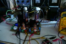
I did some more testing on the UNSET proto board last night. I'm using 5K ohm Hammond 1628SEA OPT's as 2.5 K transformers by putting the 8 ohm load on the 16 ohm tap. This is not ideal, but they are the biggest SE OPT's that I have at the moment. This arrangement usually results in loss of high frequency response, power output, and damping factor due to presence of more primary turns than needed for a 2.5K OPT. The extra wire raises the stray capacitance and winding DCR.
Despite these issues, the results are quite good for a Single Ended amp with one output tube per channel.
The output tubes are currently 36LW6's with B+ at 480 volts (limited by my 500 volt caps). I set the idle current at 120 mA per tube (max spec for the 1628SEA) for a plate dissipation of 48 watts. The 36LW6 is conservatively rated at 40 watts. It has a 2 inch tall plate compared to the 40 watt KT88's 1.5 inch tall plate, so I'm not worried running them at 48 watts. In post #31 they are just beginning to show plate color at 87.5 watts!
I made some of the usual "HiFi amp test" graphs and included them here.
The frequency response is plotted at 10 Watts power output, as opposed to the usual 1 Watt.
The THD VS Frequency is also plotted at 10 Watts. As expected the THD rises in the low bass region, that is the nature of a SE OPT, but how many low budget SE amps are under 3% THD at 20 Hz while making 10 watts?
I also plotted the usual THD VS Power output for three frequencies. 30 Hz, 1 KHz and 20 KHz. Trying to crank over 20 Watts (or any power level over 12 watts) through these mismatched OPT's at 20 Hz makes for some ugly saturation. Saturation is also the reason for the 8.21% at 22 watts and 30 Hz. The OPT's are operating at their maximum current spec.
Attachments
I spent the time I had for UNSET today just listening to it and chasing down a low level 44 KHz pulse on the output of one channel. Turns out that the clip lead that I used to ground the case of the 36 volt heater SMPS was open.
Attachments
Last edited:
I posted some of the technical details as to how the UNSET/CED technology works in post #9 here:
https://www.diyaudio.com/forums/tub...sing-mosfet-ultralinear-feed.html#post6267790
https://www.diyaudio.com/forums/tub...sing-mosfet-ultralinear-feed.html#post6267790
George, can you tell us what you have the output stage gain set to for the circuit that gave the results in post 43?
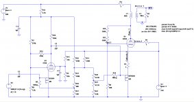
I have not gone poking around in this amp with a scope recently since it worked pretty much as expected in the sim. Here is the last LTspice run that I did, which was for a different output tube and load impedance. The sim was done with a 6DQ5 and a 5K ohm OPT. Bias current was around 100 mA.
The sim shows 32 volts P-P on the gate of the mosfet, and 800V P-P on the plate of the tube for a stage voltage gain of 25. It's going to be close to that number because the overall amp sensitivity comes close to the sim.
That circuit is close to what I used on first power up. The actual tube was a 25DN6 because I have over a hundred at an average cost of under 50 cents each.....I don't cry when I blow them up, so of course, I have never blown one. After I saw life, I did put in the 6DQ5's, and the results were similar. Ditto, several other tubes in the 25 watt dissipation class.
I put in a pair of 36LW6's with no changes other than bias, and I put my 8 ohm load on the 16 ohm taps for a 2500 ohm plate load. The maximum recommended current is 120 mA which is what I used for those tests in post #43. I find that they work a little better overall with a bit more current. The tests show a dropoff in available bass power due to saturation, but the listening tests seem to sound better as I crank up the current and voltage. I like the sound best when the tubes are glowing a dull red.....525 volts on 500 volt caps and about 150 mA makes 25 watts and sounds great.
Attachments
Very cool. I don't know how much of a contributor the input stage is to overall distortion in the amp, so this may not be worth it if it is already much more linear than the output stage, but I've had good luck CCS-loading pentodes with local feedback and then driving the feedback network from the source of the CCS. Lots of open-loop gain and local feedback makes distortion drop to almost nothing. I think that could work here. A high-value resistor in parallel with CCS can help with bias stability without degrading it too much. Some pentodes don't need it, some do in my experience. Just an idea.
I really like the B+ boost feature built into this. There's no such boost in the similar inverting approach that I've taken in the past, which is p-channel fet follower driving a shunt network.
I don't know if you've seen the approach I've been taking myself lately which is driving the input stage cathode with a p-channel fet follower with the gate driven from an output tube plate voltage divider. It's working out quite well but obviously it's a different approach from linearizing each stage separately as you are doing here (and emulating the traditional SET amplifier approach).
Could it drive a 4212 into A2?
I never met a 4212 either.......but it could push an 833A (bigger than a 4212) to 200 watts of class A2 power on 1500 volts.
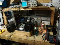
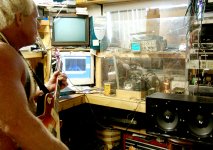
The "big PowerDrive board" was a one-off done on a piece of unclad FR4 using point to point wiring. This was mounted to a big heatsink (way oversized, but I had a box full) and is seen here to the right of the 45 tube and below the 845's. I simply removed the 845's and used one channel of this amp to drive the 833A, which was powered by an external 1500 Volt 1/2 Amp power supply ( the rack mount monster on its end to the left of the amp).
I played my guitar through this setup off and on for about a week. It could be heard two blocks away. The only issues were a tripped bench breaker twice. Note the "safety shield" between me and "it." Yes, this was some time ago. The CRT TV and computer monitor are gone.
Attachments
Hi Tubelab,
I've tried to tweak your schematic with EF86 and GU50, obtaining 10,5Wrms at 1% THD and 22 Wrms at 10% THD.
I've tried to tweak your schematic with EF86 and GU50, obtaining 10,5Wrms at 1% THD and 22 Wrms at 10% THD.
Code:
Harmonic	Frequency	 Fourier 	Normalized	 Phase  	Normalized
 Number 	  [Hz]   	Component	 Component	[degree]	Phase [deg]
    1   	1.000e+03	1.303e+01	1.000e+00	  179.45°	    0.00°
    2   	2.000e+03	5.684e-02	4.362e-03	  -81.68°	 -261.13°
    3   	3.000e+03	1.143e-01	8.768e-03	  175.14°	   -4.32°
    4   	4.000e+03	5.119e-02	3.928e-03	   89.47°	  -89.98°
    5   	5.000e+03	1.700e-02	1.304e-03	 -175.63°	 -355.08°
    6   	6.000e+03	9.272e-03	7.116e-04	  -89.37°	 -268.82°
    7   	7.000e+03	3.040e-03	2.333e-04	  177.62°	   -1.83°
    8   	8.000e+03	7.773e-03	5.965e-04	  -83.70°	 -263.15°
    9   	9.000e+03	9.023e-03	6.924e-04	    3.65°	 -175.80°
Total Harmonic Distortion: 1.069713%(1.072210%)
Code:
Harmonic	Frequency	 Fourier 	Normalized	 Phase  	Normalized
 Number 	  [Hz]   	Component	 Component	[degree]	Phase [deg]
    1   	1.000e+03	1.881e+01	1.000e+00	  179.50°	    0.00°
    2   	2.000e+03	3.315e-01	1.762e-02	  -90.94°	 -270.44°
    3   	3.000e+03	1.862e+00	9.896e-02	  177.33°	   -2.17°
    4   	4.000e+03	5.698e-02	3.029e-03	  -56.28°	 -235.77°
    5   	5.000e+03	3.998e-01	2.125e-02	   -3.54°	 -183.03°
    6   	6.000e+03	4.029e-02	2.142e-03	  101.89°	  -77.61°
    7   	7.000e+03	6.910e-02	3.673e-03	   -1.53°	 -181.03°
    8   	8.000e+03	4.663e-02	2.478e-03	   94.00°	  -85.50°
    9   	9.000e+03	9.755e-02	5.185e-03	  174.52°	   -4.98°
Total Harmonic Distortion: 10.303423%(10.304653%)
Attachments
Last edited:
Sorentos UNSEPP
I actually prototyped the GU50 version similar to Roberto's but with 6BN11 as input pentodes and a DC servo for the outputs because at least one of my GU50s (already heavily used) showed signs of thermal runaway above 30W idle.
Now here is a quick sim of a simple push-pull version, based on Roberto's.
4x the power, 40 W easily, and beyond when driven into B1.
The splitter is just a transistor concertina (2x HOT in darlington) for simplicity.
Still 1% at 10W, a little over 2% at 40W.
But to my utter surprise, the sonic signature and distortion spectrum does not change significantly for the PP-version, it still looks very similar when compared to the SE ...
I've tried to tweak your schematic with EF86 and GU50, obtaining 10,5Wrms at 1% THD and 22 Wrms at 10% THD.
[/CODE]
I actually prototyped the GU50 version similar to Roberto's but with 6BN11 as input pentodes and a DC servo for the outputs because at least one of my GU50s (already heavily used) showed signs of thermal runaway above 30W idle.
Now here is a quick sim of a simple push-pull version, based on Roberto's.
4x the power, 40 W easily, and beyond when driven into B1.
The splitter is just a transistor concertina (2x HOT in darlington) for simplicity.
Still 1% at 10W, a little over 2% at 40W.
But to my utter surprise, the sonic signature and distortion spectrum does not change significantly for the PP-version, it still looks very similar when compared to the SE ...
Attachments
My "last big tube amp" has been in the planning / dreaming stage for far too long. It's time to actually build something before I get too old to move it. I'm looking at a vacuum tube kilowatt (500 WPC) using big TV sweep tubes, probably 6 per channel. Plate voltages will be in the 650 to 700 volt range with screen voltage at 150 volts.
In that quest, I concocted an evil experiment. I got my first prototype UNSET repaired to its original status as some parts were borrowed to build the second proto. It was loaded with the biggest sweep tubes I have, the 36LW6 and tested as a two channel SE amp with the big Hammond OPT's and still made about 40 watts per channel when run at 600+ volts.
I used a small Edcor matching transformer to drive the two channels out of phase and wired a push pull OPT across both outputs. I used a sacrificial OPT for the initial test, since I have several and did not want to risk a good OPT in an experiment that could end badly.
Then I attempted to answer two simple questions by using a little Edcor matching transformer for as phase splitter and wiring a push pull OPT across the output of both channels. The unset board is unchanged, except for reducing the bias from 120 mA per tube to 45 mA.
How many tubes will it take to get 500 watts. I now know that to be 6.
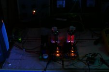
How much power (at 1KHz) can I squeeze through a $16 OPT designed for guitar amps by a battery charger company. I don't have this answer yet, but a pair of 36LW6's on 650 volts made the watt meter hit 253 watts in pretty severe clipping. THD is just under 4% at 200 watts, and 5% is at about 220 watts. I tried to take a few hand held pictures with the lights off, but that didn't work out too well. You can see the redness in the tubes at 220 watts, so 4 of them will not do 500 watts.
I started smelling something hot, so I powered down and touched a few things starting with the OPT. Yes one side was rather HOT....duh its between the output tubes and the load resistor that's eating those 220 watts (it was real hot and sitting on cardboard). The heat sink on the screen grid regulator (yes it's dropping 500 volts) was rather warm too.
After this thing cools off, I may try an expensive OPT to see how it works. The little guy in between the two 1628SEA Hammonds was used for this test. I'll use a tripod this time too.
__________________
In that quest, I concocted an evil experiment. I got my first prototype UNSET repaired to its original status as some parts were borrowed to build the second proto. It was loaded with the biggest sweep tubes I have, the 36LW6 and tested as a two channel SE amp with the big Hammond OPT's and still made about 40 watts per channel when run at 600+ volts.
I used a small Edcor matching transformer to drive the two channels out of phase and wired a push pull OPT across both outputs. I used a sacrificial OPT for the initial test, since I have several and did not want to risk a good OPT in an experiment that could end badly.
Then I attempted to answer two simple questions by using a little Edcor matching transformer for as phase splitter and wiring a push pull OPT across the output of both channels. The unset board is unchanged, except for reducing the bias from 120 mA per tube to 45 mA.
How many tubes will it take to get 500 watts. I now know that to be 6.
How much power (at 1KHz) can I squeeze through a $16 OPT designed for guitar amps by a battery charger company. I don't have this answer yet, but a pair of 36LW6's on 650 volts made the watt meter hit 253 watts in pretty severe clipping. THD is just under 4% at 200 watts, and 5% is at about 220 watts. I tried to take a few hand held pictures with the lights off, but that didn't work out too well. You can see the redness in the tubes at 220 watts, so 4 of them will not do 500 watts.
I started smelling something hot, so I powered down and touched a few things starting with the OPT. Yes one side was rather HOT....duh its between the output tubes and the load resistor that's eating those 220 watts (it was real hot and sitting on cardboard). The heat sink on the screen grid regulator (yes it's dropping 500 volts) was rather warm too.
After this thing cools off, I may try an expensive OPT to see how it works. The little guy in between the two 1628SEA Hammonds was used for this test. I'll use a tripod this time too.
__________________
Attachments
Last edited:
Previously, I got out the first iteration of the UNSET board, fixed it up and tried driving the two channels out of phase through a P-P OPT. I bought 200 of these OPT's about 20 years ago to make guitar amps for $16 each. I still have several, so I use them for experiments that could end badly, and I have destroyed or damaged only two in 20 years. One erupted in flames when a cheap Radio Shack dummy load blew open at about 150 watts with 6LW6 tubes on 750 volts. The second became a magnet when a plate to ground arc due to a couple KV on a 300 volt feedback resistor, again 36LW6's at over 150 watts output. What's in the UNSET board? 36LW6's......
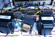
After a couple hours of beating on the setup produced no smoke, fireballs, or severe EMP events, I decided to swap out the $16 OPT for the Mother Of All OPT's. It's about the same size at the UNSET board and far heavier, rated for "400 watts @ 20 Hz, this beast should be able to wring more power out of the test amp. It's a 1250 ohm to 0-2-4-8 ohm transformer, but has been used successfully at 2500 ohms to 0-4-8-16 ohms up to 250 watts, so I hook it up.
The UNSET board is still completely stock. I haven't messed with any of the feedback paths or changed any parts, just turned down the idle current to avoid melting tubes at high B+ voltages.
Since the tubes behave as triodes, the idle current will be highly dependent on the B+ voltage. I had not tested 36LW6's at 2500 ohms before, even in pentode mode, so I started at 450 volts and 50 mA per tube and worked my way up to 630 volts at 35 mA, keeping the idle dissipation around 22 watts per tube / mosfet pair in roughly a 90/10 ratio. I was planning to try 650 volts at 33 mA (power supply max), but I never got there.
The results at 630 volts at 35 mA were far better than expected, and show that I could probably use a little less voltage in the big amp.
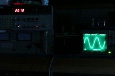
When I ran a frequency response at 100 watts test (the typical 1 watt test is just lame) some saturation was seen in the OPT.
Toroids, even big ones, are sensitive to DC and AC imbalance at low frequencies. I am using the primary of a little Edcor matching transformer as a phase inverter. It is running out of inductance and creating a drive imbalance, that I can't compensate for in the amp, so the LF results were slightly skewed. One output tube is obviously being driven harder than the other, as seen in the plates with the lights off. Even so the 100 watt +/- 3 dB frequency response is 11 Hz to 63 KHz. THD at 20 Hz was almost 4%, but remained below 1% from 46 Hz to 63 KHz. I have made measurements with these OPT's before and 63KHz is the upper 3 dB point in most cases (it's never been higher) so there are no HF limitations in the amp. Two LF poles with 1 megohm / 0.1 uF roll off the LF.
I ran a power VS THD and total current drawn from the power supply for the entire amp. Several watts were wasted in the screen regulator which dropped 630 volts down to 150 volts. Again, it blew up when attempting to hit 350 watts in severe clipping. The big amp will get a separate screen supply with current limiting to keep from killing tubes if the amp is driven to hard clipping for long periods of time. Who needs to run a 1 KW amp into clipping anyway?
Power THD total current
0.1W 0.430% 120 mA
0.5W 0.455% 120 mA
1.0W 0.462% 125 mA
2.0W 0.501% 135 mA
5.0W 0.569% 150 mA
10W 0.715% 180 mA
20W 1.15% 210 mA
50W 1.06% 310 mA
100W 0.880% 440 mA
150W 0.764% 550 mA
200W 1.366% 650 mA
250W 2.20% 750 mA
300W 6.88% unsure, PS went into I limit
350W power dropped off when screen reg blew.
As this test progressed the output tubes began to show red plate at 200 watts and got hotter at 250 watts. Peak efficiency was seen at 200 watts out, so the tubes don't like making 250 or more watts into 2500 ohms. 500 watts into 1250 ohms with 3 pair of tubes means each pair will see 3750 ohms and probably less B+.
If one channel drew 750 mA at 250 watts, two should draw 1.5 amps, or 945 watts, plus 202 watts for the tube heaters. The tube heaters will run from an SMPS, but the B+ supply is still unknown. Weight is the primary driving factor there. It all needs to draw less than 1800 watts to use a US spec power outlet (120 V @ 15 A)
The next step will be to make a proper phase inverter, then play with the feedback.
After a couple hours of beating on the setup produced no smoke, fireballs, or severe EMP events, I decided to swap out the $16 OPT for the Mother Of All OPT's. It's about the same size at the UNSET board and far heavier, rated for "400 watts @ 20 Hz, this beast should be able to wring more power out of the test amp. It's a 1250 ohm to 0-2-4-8 ohm transformer, but has been used successfully at 2500 ohms to 0-4-8-16 ohms up to 250 watts, so I hook it up.
The UNSET board is still completely stock. I haven't messed with any of the feedback paths or changed any parts, just turned down the idle current to avoid melting tubes at high B+ voltages.
Since the tubes behave as triodes, the idle current will be highly dependent on the B+ voltage. I had not tested 36LW6's at 2500 ohms before, even in pentode mode, so I started at 450 volts and 50 mA per tube and worked my way up to 630 volts at 35 mA, keeping the idle dissipation around 22 watts per tube / mosfet pair in roughly a 90/10 ratio. I was planning to try 650 volts at 33 mA (power supply max), but I never got there.
The results at 630 volts at 35 mA were far better than expected, and show that I could probably use a little less voltage in the big amp.
When I ran a frequency response at 100 watts test (the typical 1 watt test is just lame) some saturation was seen in the OPT.
Toroids, even big ones, are sensitive to DC and AC imbalance at low frequencies. I am using the primary of a little Edcor matching transformer as a phase inverter. It is running out of inductance and creating a drive imbalance, that I can't compensate for in the amp, so the LF results were slightly skewed. One output tube is obviously being driven harder than the other, as seen in the plates with the lights off. Even so the 100 watt +/- 3 dB frequency response is 11 Hz to 63 KHz. THD at 20 Hz was almost 4%, but remained below 1% from 46 Hz to 63 KHz. I have made measurements with these OPT's before and 63KHz is the upper 3 dB point in most cases (it's never been higher) so there are no HF limitations in the amp. Two LF poles with 1 megohm / 0.1 uF roll off the LF.
I ran a power VS THD and total current drawn from the power supply for the entire amp. Several watts were wasted in the screen regulator which dropped 630 volts down to 150 volts. Again, it blew up when attempting to hit 350 watts in severe clipping. The big amp will get a separate screen supply with current limiting to keep from killing tubes if the amp is driven to hard clipping for long periods of time. Who needs to run a 1 KW amp into clipping anyway?
Power THD total current
0.1W 0.430% 120 mA
0.5W 0.455% 120 mA
1.0W 0.462% 125 mA
2.0W 0.501% 135 mA
5.0W 0.569% 150 mA
10W 0.715% 180 mA
20W 1.15% 210 mA
50W 1.06% 310 mA
100W 0.880% 440 mA
150W 0.764% 550 mA
200W 1.366% 650 mA
250W 2.20% 750 mA
300W 6.88% unsure, PS went into I limit
350W power dropped off when screen reg blew.
As this test progressed the output tubes began to show red plate at 200 watts and got hotter at 250 watts. Peak efficiency was seen at 200 watts out, so the tubes don't like making 250 or more watts into 2500 ohms. 500 watts into 1250 ohms with 3 pair of tubes means each pair will see 3750 ohms and probably less B+.
If one channel drew 750 mA at 250 watts, two should draw 1.5 amps, or 945 watts, plus 202 watts for the tube heaters. The tube heaters will run from an SMPS, but the B+ supply is still unknown. Weight is the primary driving factor there. It all needs to draw less than 1800 watts to use a US spec power outlet (120 V @ 15 A)
The next step will be to make a proper phase inverter, then play with the feedback.
Attachments

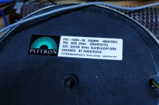
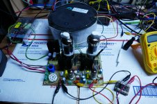
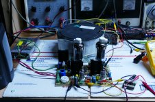
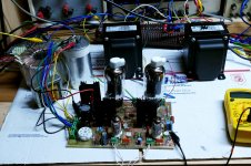
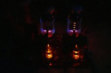
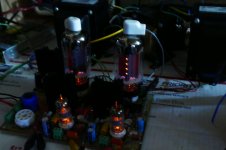
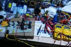
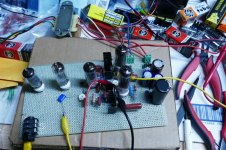
I briefly mentioned a little push pull amp that I made with 50C5 tubes in Post #39. It is seen here (pics#2 and 3) making exactly 20 watts from a pair of 50C5's after running all night long at full power. These were a common output tube in the AA5 vacuum tube radios that were common in the 50's and early 60's.
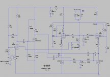
I have received a PM and a couple emails asking about the 50C5 board, it's origins, and where to "find" the schematic. The schematic for complete amplifiers will not be found on the internet yet, because it is new technology and very few complete amplifiers exist yet. The perf board amp seen here, and in post #39 was made up as I went along, but heavily based on an LT Spice simulation. I have not made a schematic of the complete board containing the amp, power supply, and guitar preamp yet since the preamp section remains unfinished and some component values were tweaked as the amp was tested and debugged.
The idea behind this board is to make 20 clean watts for the least possible cost, then stick a guitar preamp in front of it with the ability to drive it well into clipping. I need a new guitar amp, and if it eats my lousy guitar playing at full crank, then it is ready for less severe HiFi duty.
Yes, the SSE, TSE, and SPP have all served duty as guitar amps early in their development. I still have an SSE that has the channels driven out of phase from a little DIY vacuum tube guitar preamp with PI and wired like the UNSET above. It runs a pair of Chinese 6L6GC's and makes 50 watts.
The LT Spice schematic is included, and it is remarkably similar to the sim in post #54. It does use some unconventional drive circuitry, and I would NOT ATTEMPT to build something like this if you do not understand how it works. I blew up a lot of parts in the quest to get this right.....ever see a vacuum tube EXPLODE? I did when trying to get a little too much power out of one....OK, way too much power due to a stupid arithmetic error.
I will post more about this technology, and condense the info that I have already shared about it when I have the time.
I went to my 85 year old neighbors aid last night when he had fallen in his house, as I have done a few times in the last few weeks. He is now recovering in the hospital. I just found out that other people in their house last night have tested positive for Covid today. On the chance that my wife and I are at risk, I will spend the next few days taking down the Christmas decorations and performing other tasks that require ladders and other physical dexterity skills.
Attachments
Thanks.
So far my older neighbor Joe is still in the hospital with pneumonia. He has had surgery to put a drain in one lung, and is "doing better." Communication with the hospital staff has been poor at best. The hospital is currently at capacity with Covid cases. We know that Joe was rapid tested for Covid before being admitted to the hospital. The rapid response test does not find all positives, especially early on.
I spent nearly an hour with his son getting him out of the basement after he collapsed and into an SUV and to the hospital. His wife was in the kitchen with some of the grandkids and great grandkids. The large extended family were all in that house new years day. The granddaughter, her husband, and their son have all developed symptoms and tested positive. So far nobody else has any symptoms, so can not get tested. All persons present on Jan 1 are now on a day 6 of a 14 day quarantine. My wife and I were not there, even though we are relatives.
In an effort to get a handle on the recent explosion in Covid cases here, the county health department was giving free tests to anyone. Once the hospital reached capacity, they quit testing......maybe to improve the numbers published in the local newspaper that show an 8% positive rate.
- Home
- More Vendors...
- Tubelab
- UNSET is coming?