Off-Board Sockets
Pads just make it easier...for example, I had an SSE configured for BOTH 6L6-family tubes AND the 6AV5 sweep tube obviously not at the same time (ie 6L6 parallel with 6AV5!). I just inserted the off-board wires alongside the socket pins.
Without the sockets in there, you do need a big glob of solder (as you point-out), but it would be a lot neater with pads.
Also handy for pulling-off test points, or using alternate fils voltages, eg 12/25v sweep tubes (although trace-cutting would be required if power and drive tubes are different fils voltages).
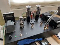
I used a well-abused SSE board for off-board socket experiments (see photo) but didn’t pay much attention to wiring “hygiene” (e.g tight-twisting the fils wires).
If I did this today, I’d use smaller gauge wire and route it under the board with fils wires twisted and isolated. High temp insulation (eg TEFLON or similar) is strongly recommended; hanks are available on FleaBay.
Pads just make it easier...for example, I had an SSE configured for BOTH 6L6-family tubes AND the 6AV5 sweep tube obviously not at the same time (ie 6L6 parallel with 6AV5!). I just inserted the off-board wires alongside the socket pins.
Without the sockets in there, you do need a big glob of solder (as you point-out), but it would be a lot neater with pads.
Also handy for pulling-off test points, or using alternate fils voltages, eg 12/25v sweep tubes (although trace-cutting would be required if power and drive tubes are different fils voltages).
I used a well-abused SSE board for off-board socket experiments (see photo) but didn’t pay much attention to wiring “hygiene” (e.g tight-twisting the fils wires).
If I did this today, I’d use smaller gauge wire and route it under the board with fils wires twisted and isolated. High temp insulation (eg TEFLON or similar) is strongly recommended; hanks are available on FleaBay.
Attachments
Not sure why we need these secondary pads. If someone wire remote sockets, the primary holes can be used, rigt ? or is this only because their large diameters makes it difficult to solder wires ?
They are not secondary pads. The SSE, TSE-II, and SPP boards have their tube sockets connected as the schematic shows. This restricts their use to a fairly narrow range of tubes. The SSE uses any of several common audio tubes that happen to have the same pin configuration. The TSE and TSE-II uses 4 pin tubes, most of which have the same pin configuration. The SPP however can use only EL84's and 6CW5's. There are dozens of other 9 pin tubes that can work in that design, but using them requires hacking up the PC board to change it's wiring.
Octal based TV sweep tubes come in an enormous combination of non compatible pin configurations. The UNSET can also work with non sweep tubes. I had one running with KT88's. This makes for either a large selection of different boards, or some method for user configuration.
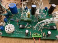
One of the many long delays with the UNSET board was arriving at the current method of making the board useful with nearly any octal tube. The current method has a pair of octal sockets on the board with each pin connected only to the pad on the board right next to it. During the build process jumper wires are used to configure it for a given tube pinout. The grids and cathode are jumpered to the horizontal busses running across the board, while the heaters are jumpered to the pair of vertical busses running between the output tubes.
To use the board with remote output tube sockets, the board mounted sockets are left out and the remote sockets are wired to the most convenient pad on each bus.
The output tubes and driver tubes have their heater circuits isolated from each other so that different heater voltages can be used.
Georges thanks for the clarification ! This is an astucious design and i look forward to build an UNSET in my future. After my move is sorted out, and the other 2 SSE I have on the bench are finished.... oh and the 2 pairs of speakers in back-order... To many interesting projects, too little time.
")
Georges thanks for the clarification ! This is an astucious design and i look forward to build an UNSET in my future ...
A new word, thank you!
I was wondering if it would be worth having a seperate rectifier sub-board, suitable for different projects, and leave a bit more real estate on the amp board?
I also think it is quite nice with a symetrical layout, and then there are also alternative options available for the PSU.
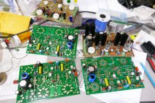
I finished stuffing one board last night.
I have found three mistakes in the PC board design. That's what I get for trying to rush things and sending a board out without making a DIY proto board here first. It turns out that a DIY proto would not have caught any of the mistakes since two are on the silkscreen layer, and one has to do with hole size.
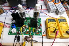
I had a few minutes this morning, so I just hooked it up to a bench power supply and flipped the switch, expecting to find some more of my mistakes.
There was no big bang. The board powered right up, and delivered 10 to 15 WPC after adjusting the bias pots. There needs to be some parts value tweaking and quite a bit of testing, but.....
I still want my 30 WPC UNSET amp, so it dawned on my that I should be able to make a mono block PSE board with the UNSET in a manner similar to those I made with the SSE and TSE. More experiments will come, but probably not until Sunday.
I have found three mistakes in the PC board design. That's what I get for trying to rush things and sending a board out without making a DIY proto board here first. It turns out that a DIY proto would not have caught any of the mistakes since two are on the silkscreen layer, and one has to do with hole size.
I had a few minutes this morning, so I just hooked it up to a bench power supply and flipped the switch, expecting to find some more of my mistakes.
There was no big bang. The board powered right up, and delivered 10 to 15 WPC after adjusting the bias pots. There needs to be some parts value tweaking and quite a bit of testing, but.....
I still want my 30 WPC UNSET amp, so it dawned on my that I should be able to make a mono block PSE board with the UNSET in a manner similar to those I made with the SSE and TSE. More experiments will come, but probably not until Sunday.
Attachments
Tube Spotting -plus- 46 in a TSE
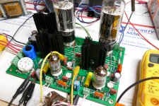
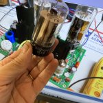
So here’s me, trying to figure-out what top-cap sweep tube that is…
I think I’m pretty close, but not quite….
Also, tbx to W5JAG for reminding me about 5-pin to 4-pin adapters. Ordered a few pairs of “kits” from Angela ($7 per each) which required soldering wires and a few drops of cyanoacrylate. After about an hour of rectifier and First Cap rolling, I got EXACTLY 250Vp and 22mA bias. I sure like those 46s; maybe not better than 45s, but they sure are spritely in triode connection. Gonna leave their gangly butts in there for a while. I’m 68 & have 3 pairs of 46s NOS/NIB. Pretty sure that’s a “lifetime supply”.
Attachments
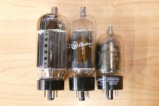
Hey, that little puppy better stay on the sidewalk, or it will be run over by the big dogs. The tube in my board is the middle one in the picture. The big boy on the left can eat 80 watts or so before redness sets in. The 6BQ6GA/6CU6 gets redfaced at about 25 watts. It has the same guts as the 6AV5GA.
Attachments
Last edited:
- Home
- More Vendors...
- Tubelab
- UNSET is coming?