It appears that a few builders would want something like the two boards I have been using.
I'm totally ready to use whatever you want to put out there (here).
I figure that your generosity in working all this out and putting it into a board for us likely nets you something less than ¢50 per decade of your considerable (and it should be noted, pyrotechnically entertaining) experience. Whatever suits you suits me. And thanks in advance !
..to avoid using those precious 5842 drivers. What sort of drive are we talking about... Are we gonna need tube shields for our pentode?
The drive VOLTAGE level required depends on the choice of output tube. The single board design that I am currently working on is limited to octal tubes. Another design for a different output socket could be done if desired, but let's see how this goes. I have run this board with everything from a 6V6 to a 36LW6. The drive voltage requirements are also highly dependent on the feedback resistors used to "trioderize" the pentode.
The board contains a 9 pin socket wired to accept any tube with the 9AQ, 9PM, 9NW, 9GK, 9BF, and 9AU pinout. Some type numbers are 6EJ7/EF184 6EH7/EF183 6GK7 6JC6 6JD6 6HM6 6KT6 6HT6 6HA6 6HB6 6KY6 6GK6 12BY7A 12GN7 12HG7 12HL7 11HM7 6686 E81L 6BR7 6059.
No shield should be needed on most of these tubes since they are internally shielded.
The version with off board sockets will have more room so a jumper option will be added to also accommodate 9EQ, 9G, 9NX, 9BL and 9CV tubes, just in case someone wants to stick D3A's in this thing. I have two of them, but haven't tried them yet. The extra space will also allow for inclusion of more feedback options that will be optional like the plate to plate resistors on the UD boards.
I've taken to stuffing little notes on bits of index cards into my storage boxes so I get SOME clue why I bought what I bought.
Similarly, I try to write Project part numbers on the index cards in the plastic bags I sort resistors into.
It rarely works, but The Plan gives some comfort.
Similarly, I try to write Project part numbers on the index cards in the plastic bags I sort resistors into.
It rarely works, but The Plan gives some comfort.
I've 4 D3As and have no good idea what project I got them...ah, i think Sy's phono pre-amp.
I bought two some time ago from Ask Jan First in Europe for use in that phono stage. Before I built it I got some high grade TI opamps and built a phono stage that sits inside the turntable right at the base of the tone arm. The D3A's have never seen power.
George:
(a) what did you do for RIAA correction? Passives between stages?
(b) what gain? i.e. will it handle Moving Coil cartridges? I have hesitated to go to MC carts simply because I haven't found a good (read: CHEAP) way to get the gain. Good step-up transformers are ridiculously expensive, and getting that much gain out of tubes is fraught with potential disaster.
(c) This (opamp phono stage INSIDE turntable housing) sounds like a great idea if only because you're eliminating cable capacitance before the gain stage.
(d) Y'all got a schematic?
I simply copied the circuit shown in the front page of the data sheet, laid it out on a tiny SMD board along with a tiny bipolar 12 volt power supply also made with TI parts and stuffed it into the base of my 80's vintage Technics SL-D2. It is made for MM cartridges, and I'm still running an 80's vintage ADC.
Are there better designs out there? Probably. Is this better than my current hearing? Definitely.
Are there better designs out there? Probably. Is this better than my current hearing? Definitely.
Attachments
Last edited:
Jeebus! what did the whole thing cost about $12 if that? I went down Sy'S path as I was given a Denon 103R of unknown age and usage. I think it was used lightly, if at all. A good friend belonged to the Audiophile 'object of the month' club, no significant other - confirmed bachelor type.
Last edited:
Jeebus! what did the whole thing cost about $12 if that?
I was a research engineer in a Motorola plant at the time. My total cost for that one off "prototype" was zero.
I did "pizza boards" (everything but anchovies) almost every week to test out ideas, evaluate new silicon, or perform simple functions. We had a PC board fab and an SMD assembly line in house. I simply tacked a little preamp on a corner of one of my boards. Many vendors gave us sample parts, even if they knew they were being used for home projects.
Back in the mid 90's the National Semiconductor rep gave me a whole box full of parts to build a programmable guitar amp. All the controls were connected to a PIC chip which then fed some SPI controlled pots, an EQ chip and some tone control chips. Find a sound you like, save it. Recall it later by pushing a few buttons....neat stuff in the mid 90's. I made one for his kid too. Still have some of those old chips, including the LM3886T power amp chips.
Nat Semi was good about sending out samples, even to hobbyists.
If there was a part I could not find, I would write them asking where I could buy one or two pieces of the part. Invariably, I would get a few samples of the part back in the mail.
I still have some LM1596H and some LM1035 (6?) and LM1040 that I got that way.
My only concern about off board tubes would be stability. But most power tubes are low mu, so probably not an issue.
Octals are fine (for now).
How flexible are the pin configurations?
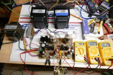
The current board configuration has a pair of octal sockets with a jumper hole for each pin. There are also buses for H, K, G1, G2 and P nearby so that the board can be configured for any octal tube......well any octal tube capable of amplifying an audio signal.
These can be seen in this picture of the prototype. The white / green wires connect the heater pins to a par of PCB runners running between the output tubes. The brown wires connect the grids, and the orange wires connect the cathodes. Multiple holes are provided to allow for short wires with many different tube types.
The heater terminals for the driver and output tubes are separate since most driver tubes are 6.3 volts (or less) while most of the cheap sweep tubes come in odd voltages.
Obviously these wires can run to external sockets which is being tested now.
Attachments
This is exciting and thank you! Can’t wait for the boards! I had hoped for a more modular approach, but if you determine differently we will work whatever you bless.
I have ordered some 6DQ5 tubes in anticipation of the boards, since I think you favor 8-pin 6DQ5 tubes. If I could read the tealeaves I could make money in pre-buying the market. Hopefully you can too. Whow, we’re in this stockmarket.
I have ordered some 6DQ5 tubes in anticipation of the boards, since I think you favor 8-pin 6DQ5 tubes. If I could read the tealeaves I could make money in pre-buying the market. Hopefully you can too. Whow, we’re in this stockmarket.
Last edited:
I had hoped for a more modular approach.
I have ordered some 6DQ5 tubes in anticipation of the boards, since I think you favor 8-pin 6DQ5 tubes.
The modular approach is coming. It unfortunately requires laying out, several new boards, while the existing board is well, already existing. Still it takes me a bunch of time to go over all the little details needed to make it worthy of the Tubelab name. If all goes according to plan I may send it to fab later next week.
Yes, the first board will use octal tubes. I must sell enough of them to pay for the next version or versions. Octal tubes are available world wide, while many other popular sweep tubes are not.

..... The quality goes in before the name goes on.
I have heard that somewhere before.......from the same people who had "hand-wired chassis."
Beats the Quasar with the (doesn't)works in a drawer. If it didn't work, just keep opening and slamming the drawer until it did....assuming the tuner was actually passing a signal. In that case just keep changing the channel until you get one that works. I got pretty good at throwing a shoe at the drawer on mine. I could "fix it" from across the room.
In Other News: LME49720 is now OBSOLETE.
I'm queuing-up my bi-weekly Mouser order, so I went looking for a handful of the TI LME op-amps to fool around with.
Turns-out the whole LME audio opamp line has apparently been obsoleted (admittedly after a pretty long run as these things go). Looks like TI is facing huge competition in this market from the usual suspects. Plus, IIRC, the LME line was originally a NATIONAL product line, so sayonara, toodles, buh-bye, don't let the door hit you in the Dual In-Line Package.
Mouser still has many hundreds in case folks want to stock-up on a cheap super-low distortion dual op-amp at ~$2.50 each. Two of 'em will make a stereo MM phono preamp. Add that wonky glassmat motorbike battery in the garage, and you've got a noiseless phono preamp. Heck, the connectors will cost more than the opamps.
Just sayin'.
Which reminds me; probably ought to increase my back-stock of 10M45s, 'cause you never know...
I simply copied the circuit shown in the front page of the data sheet, laid it out on a tiny SMD board along with a tine bipolar 12 volt power supply also made with TI parts and stuffed it into the base of my 80's vintage Technics SL-D2. It is made for MM cartridges, and I'm still running an 80's vintage ADC.
Are there better designs out there? Probably. Is this better than my current hearing? Definitely.
I'm queuing-up my bi-weekly Mouser order, so I went looking for a handful of the TI LME op-amps to fool around with.
Turns-out the whole LME audio opamp line has apparently been obsoleted (admittedly after a pretty long run as these things go). Looks like TI is facing huge competition in this market from the usual suspects. Plus, IIRC, the LME line was originally a NATIONAL product line, so sayonara, toodles, buh-bye, don't let the door hit you in the Dual In-Line Package.
Mouser still has many hundreds in case folks want to stock-up on a cheap super-low distortion dual op-amp at ~$2.50 each. Two of 'em will make a stereo MM phono preamp. Add that wonky glassmat motorbike battery in the garage, and you've got a noiseless phono preamp. Heck, the connectors will cost more than the opamps.
Just sayin'.
Which reminds me; probably ought to increase my back-stock of 10M45s, 'cause you never know...
Zenith hand wired stuff for a long time. My 1000 and 3000 series Trans Oceanics are point to point wired. I'm pretty sure my 7000 series is as well, but I have not been able to find it lately ...
My grandfather that got me into ham radio was a Hallicrafters / Zenith guy ...
My grandfather that got me into ham radio was a Hallicrafters / Zenith guy ...

- Home
- More Vendors...
- Tubelab
- UNSET is coming?