Small steps at the moment I am afraid or there could be divorce! Lol ")
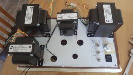
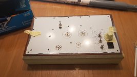
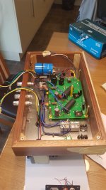
I drilled the holes for transformers today and ordered screw washers boltsvetc for them. I also ordered some 12mm grommets for the wires under the trans. When these come I can make up the top plate and atart to wire it. I have shifted the choke up towards the righthand OPT rather than being central betweenbthe 2 OPT 's itbis now central betweenbthe kt88's and this gives me better clearance and Ithinknit looks better.
I have sat the tubes in the holes to get a flavour of how its gonna look.i.am not planning on tworectifiers bit the 12ax7 falls through the hole.
Matt
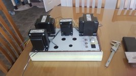
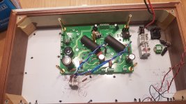
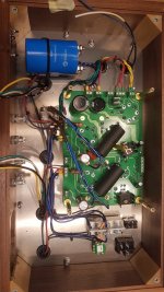
Ok had a day off today. Managed to wire in my resistors & selector switch. I am pleased with this it works well I get these readings in ohms L is left channel R is right channel.
Position1 L 554, R 555 for kt88
Position2 L743 R745 for 6p3se,
Position3 L674 R677 for EL34
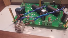
I am a little concerned about the position of the resistors and the proximity of the wires hope they don't get too hot. The resistors are 5W and the wire is high temperature stuff.
Unfortunately I drilled the hole for the switch in the top plate in the wrong place. I had to move it. I am thinking of making a plate with the valves andcresistor values to cover it. Either that or I buy a new part from hammond and start again using mine as a template.
Position1 L 554, R 555 for kt88
Position2 L743 R745 for 6p3se,
Position3 L674 R677 for EL34
I am a little concerned about the position of the resistors and the proximity of the wires hope they don't get too hot. The resistors are 5W and the wire is high temperature stuff.
Unfortunately I drilled the hole for the switch in the top plate in the wrong place. I had to move it. I am thinking of making a plate with the valves andcresistor values to cover it. Either that or I buy a new part from hammond and start again using mine as a template.
Attachments
Last edited:
A good day today.
Any comments or feedback welcomed. Thanks
Matt
Any comments or feedback welcomed. Thanks
Matt
Attachments

Last edited:
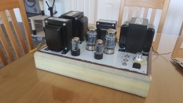
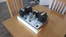
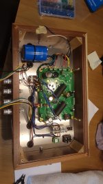
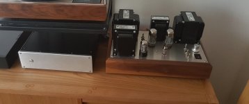
95 % built now. ������
Sounds superb and it's only going to get better as things bed in etc. The cathode resistor switching seems to be working well.
Touch wood no issues so far, pictures of It with kt88 and 6p3se's the 88's look nicer but for my taste the 6p's have the edge on sound so far.
Things left to do. 1)re wire the power input wiring with thinner cable and make it look nicer too. 2)Make a base and fit rubber feet. 3)Change nuts and bolts on traffo' s to studs with nice acorn nuts. 4)Make a plate to cover the hole I drilled in error that has the resistor values on. 5.)At a later date make a cage for the valves to be enclosed.
Incidentally I changed the switch for the inputs to a Switchcraft on fro Hifi collective and I have no cross talk now either.��
Cheers all
Matt
Hallo Matt, can you explain what values you use to get the resistors & selector switch to work ? would like to build like you but dont know the values for basic resistor on the board + the 3 different values you need to use to have different tubes whit there values.
//Tomas
//Tomas
Hello. I cheated a bit on resistor values. I used an online calculator to get the values that I wanted to be honest. You need to make sure that one is fixed in to the board otherwise there is a risk of damage. You can then switch resistors in parallel to get the values that you want for your desired tubes. My b+ is approx 445v so I looked at George's simulations for 5k OPT's and decided on values of 560ohm kt88, 750ohm 6p3se, 680ohm EL34...... From memory I fixed the highest value resistor into the board (750 ohm) and switched other resistors in parallel to get my desired resistance E.g. 2.2k gave me approx 559 for kt88, and 7.2k gave me approx 679 for my EL34.
Hope this makes sense so I used 6 resistors in total 3 on each channel in the following format. 1 fixed in position on the board 750ohm and then the other two (2.2k & 7.2k) switched in parallel to give me approx 560 ohm & 680 ohm options too.
Hope this makes sense so I used 6 resistors in total 3 on each channel in the following format. 1 fixed in position on the board 750ohm and then the other two (2.2k & 7.2k) switched in parallel to give me approx 560 ohm & 680 ohm options too.
- Status
- This old topic is closed. If you want to reopen this topic, contact a moderator using the "Report Post" button.
- Home
- More Vendors...
- Tubelab
- Matts Tubelab SEE