I have had similar fun and games.
I fitted my choke under the top plate, and also have the option to fit the power transformer under the top plate too, since it is a toroid.
With that layout the power switch is going to be behind a hot rectifier tube, between the choke, and maybe not so easy to turn of the power in a hurry.
I decided that the bells and whistles - the options for pentode vs triode, FB on/off, etc, could be experimented with 'on the bench' but to keep the basic layout as simple as possible. For instance, what would happen if one of the switches was toggled by accident? I managed to turn off my central heating pump in the middle of winter because that switch was next to the 'night temperature reduction on/off' switch. [it was -18C indoors when I got back from my Xmas break, and the water from the split radiators had frozen before hitting the floor].
I also fitted a fuse next to the power switch, and a light to indicate HT on.
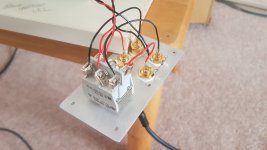
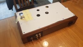
Made a switched input panel today. See pictures and have used a copingvsaw to cut a hole for the Iec invthe walnut. Tested the switched IEC but it has when I switch over from the active input to the one not being used I still hear very low level music fromvthe source o input. I think tgatthis could be cross talk invthe switch. I am not sure it matters as I will only use one source at a time but it might just niggle me knowing that it does this. Is there a way to eliminate this. PICS of the rig attached I have painted it satin black too.
Thanks Matt.
Thanks Matt.
Attachments
Last edited:
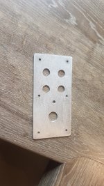
I started making a template from gash aluminium yesterday to mock up the top plate. I wanted to see how well my hole punches would work. The punches work well but after I made the template based on the printout from the tubelab site it didn't fit over my tubes. I measured the printout and it turns out it is 5mm shorter in both directions than my board. This will cause an issue with the layout and means that my Opt's will not fit behind the tubes, well not wit any clearance. Options are, revert to my original layout, or move the Opt's back by hangingthem over the back by 10 mm or so. This will give loads of clearance and could be achieved fairly simply by drilling into the wood from the top and a epoxying in some 5mm studding to bolt the Opt's to, or making up dome small righr angle brackets to fit on the back panel that allow me to do this. Hmmm!
Matt
Matt
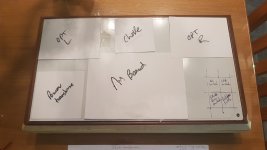
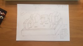
I have re arranged things I can get away with not overhanging the Opt's If I place the choke between them. I was shying away from this as I thought it would look odd. I have done a quick rendering though and I now think that this layout looks good. It is perfect for wiring up too, the switches are all in one place and away from the hot tubes.. I think that this is the way to go. ")
Matt
Matt
Attachments
Last edited:
I think I will just connect 8ohm taps to speakers as I can't get clarification on whether connecting the 4ohm taps to binding posts as well could cause damage to the OPT's. I was hoping to do this so I could connect speakers to 4 or 8 ohm taps depending on speaker type.
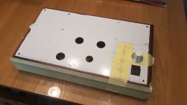
I have started the top plate and filed out a rectangular hole for the power switch, I have used the qmax type punches to cut holes for the valves . They worked superbly and saved me hours of drilling and filing, best £20 I have spent for a while.
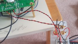
I notice one of the builders ( I think he is called Russ\Rknize -he has the really nice blue and silver sse based on the car amp look) has added test points ( banana jacks ) for his cathode resistor voltages. Due to the weight of my amp I am wondering If I should copy his idea as this could save me from having to lift the amp some in the future. Is this simply a case of connecting a Jack to ground and then a Jack to esch of the cathode resistor, if so what sort of voltages are involved and are there any safety precautions to be added on top of this.
Thanks
Matt
I have started the top plate and filed out a rectangular hole for the power switch, I have used the qmax type punches to cut holes for the valves . They worked superbly and saved me hours of drilling and filing, best £20 I have spent for a while.
I notice one of the builders ( I think he is called Russ\Rknize -he has the really nice blue and silver sse based on the car amp look) has added test points ( banana jacks ) for his cathode resistor voltages. Due to the weight of my amp I am wondering If I should copy his idea as this could save me from having to lift the amp some in the future. Is this simply a case of connecting a Jack to ground and then a Jack to esch of the cathode resistor, if so what sort of voltages are involved and are there any safety precautions to be added on top of this.
Thanks
Matt
Regarding Q-max punches - I ordered mine from rapidonline for about 7 quid each, and you get free delivery if you can spend 30 quid.
It is worth getting the 10mm one too, because then you don't have to drill a 10mm hole to punch the bigger holes, and drilling anything over about 6mm is not an easy task, especially with steel.
If you get a 18mm, then you can flush mount noval sockets on the top plate, if you ever feel the urge to do point to point wiring.
They also had some 90uF 600v motor run capacitors on clearance when I bought my punches.
Don't mean to boast but 3 days this weekend in uk. ( bank holiday Monday ).
Trouble is I am getting minor beef about parts in the house, and spending too.much time behind the soldering iron. None the less better cool it for a while...... Might get some time over the weekend but not as much as I would like.�� Have to hope she goes shopping or something.
Trouble is I am getting minor beef about parts in the house, and spending too.much time behind the soldering iron. None the less better cool it for a while...... Might get some time over the weekend but not as much as I would like.�� Have to hope she goes shopping or something.
50k attenuator arrived from China yesterday. Apart from nuts and bolts I have all the parts that i require now. On the subject of nuts and bolts does any one now the size and thread pattern of the Hammond bolts that they use to secure their transformers together. I wasthinking about buying studs and nice bolts to replace the screws.
- Status
- This old topic is closed. If you want to reopen this topic, contact a moderator using the "Report Post" button.
- Home
- More Vendors...
- Tubelab
- Matts Tubelab SEE