all of which would work in the SSE......someone built an SSE with a 6DQ6 or some other tube with a plate cap.
I have tested all of the tubes you mention in the SSE with the exception of the KT99, I have never seen one of those. There are a few builders who have used the KT120 and possibly the KT150. Their exploits are somewhere in the Tubelab forum.
Myself and W5JAG have stuck a lot of tubes into the SSE that were never meant to be there with varying results including blown up parts. The 6DQ6 does have a compatible pinout but requires far too much bias to make it work. The cathode capacitor will explode unless it is uprated to at least 100 volts. The 6BQ6 can be made to work, but again it's not optimal. W5JAG had a 6146 or a 2E26 in there. Both have plate caps.
The real reason that I put the first multi cathode resistor into the SSE is for the flexibility to run different tubes, but I still wound up using a KT88 most of the time and an EL34 quite often.
It is advantageous to be able to use different bias settings for different speakers and music choices......Want to shake the walls with some Pink Floyd, hook up the Open Baffle speakers with 15 inch woofers, run the KT88's in UL mode with the cathode feedback and solid state rectifier turned on and crank the bias current up to about 100 mA. I don't like leaving the amp turned up this hot all the time since I am way over the current spec for the power transformer, and the dissipation spec for the KT88. I run it much more conservatively most of the time. Turning up the tube current does very little for the power output, but it does increase the damping factor which helps the bass on some speakers.
Want to listen to Norah Jones, Enya, or Daina Krall, stick it an EL34 run in triode mode, hook up the Yamaha NS-10's and run the tube at about 60 mA.
Just switching in different resistors with a switch isn't a good idea since it's possible to operate the amp with no resistor at all making live very uncomfortable for the cathode bypass cap. I put a 1K ohm 5 watt resistor in the board, then used the switch to add different resistors in parallel with the 1K. If you do it this way, the added resistors can usually be 2 watts.
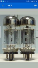
A picture of the 6P3S tubes might be helpful. The thin, straight bottle, Soviet tubes are probably about a twenty watt tube.
The - E variants might be a few watts more, but I doubt they are a thirty watt tube. The ones I have were marketed by Sovtek as 6L6GB.
Some, but by no means all, of the Chinese 6P3S border on indestructible. The small coke bottle tubes are really tough, but it has been a long time since I have seen any of those for sale. I use the current manufacture straight bottle Chinese 6P3S as 6L6GC in regulated power supplies. These are marked as 6L6GC and probably are a thirty watt tube, but I lose about 10 volts of output compared to American 6L6GC, so there is something about them that is a bit off.
edit: I have some Chinese 6P3S that Shuguang marked as 6L6WGB. There are a lot of different tubes in the 6P3S type family.
Last edited:
Hello, I had seen an earlier post where tubelab advised to leave the cathode resistor in the board, so l was planning to work out values to leave one in board and have two other options on the switch to avoid fried resistors. Interesting about the 6p3se's. I read an article saying that they are rugedised and hard as nails and red plate at over 42w so are safe for operation up to 35w. Thanks both for the helpful comments I will try and post a pic of my russian tubes.
Matt
Matt
Attachments
Last edited:
W5jag thanks, yes looking in to this some more you are correct, although opinions seem divided on this tube. I found a Russian spec sheet that quotes 20.5w but apparently the Russian specs are normally conservative and it seems most people run these at 21w and get good results. With that in mind looking at tubelab Sims for 6l6GC I should start out way higher than 560r somewhere more like 750 or 820r. I realise I was quoting "k" earlier for my values and just double checked, I am using 560r with the kt88's. Hope I am along the right lines now, so I could fix my 560r 5w into the board and switch smaller 2 or 3w resistors to achieve 680r for el34 and 820r for 6p3se.
Just looked up resistors in parallel. I would need to fix the highest values. 820r to the board and switch 3w resistors of higher values to get the appropriate outcome. Eg with 820r in board I would switch 1.8k in parralel to achieve 563ohms resistance. I think that this is correct.
Eg with 820r in board I would switch 1.8k in parralel to achieve 563ohms resistance. I think that this is correct.
I didn't check the math, but this is the right idea.
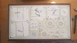
Started mocking up with cardboard cut outs. The Op trans are huge though so it will be tight. It is the larger case whatever size that is. Ideally it would have handles too but i think this will ruin the look of it.The binding posts are long reach so no problems there but I will Need to make an alluminium plate Forvthe rca as they are only short reach.
Matt,
You got big iron in your tube amp!
Slightly bigger chassis with 14" depth - does that help?
1444-17143 Hammond Manufacturing | Mouser
You got big iron in your tube amp!
Slightly bigger chassis with 14" depth - does that help?
1444-17143 Hammond Manufacturing | Mouser
Appreciated. I really like the Wallnut hammond as it will go with my Walnutt TT. If that doesn't work out it may well be helpfull though, fingers crossed it will workout. I have seen someone who has done it with the big Edcores so hopefully will work out.
Next dilemma is back to the speaker outputs. To get the correct negative feedback fo CFB I have got black wire from the OPT going directly To the speaker binding post and the yellow wire 8ohm going to the board. I was intending to wire in separate binding post a for 4 & 8 Ohms speakers. I am thinking that this could damaged the OPT now if I did this and that if I ever buy a set of 4 ohm speakers I would need to do a minor rewire instead. Am I correct? Can anyone confirm this?
Cheers
Matt,
Let me try to clarify (hopefully!") ) the question:
) the question:
1. You are planning to run the SSE in triode mode with CFB
2. With CFB wiring, your common (black) and 8 ohm (yellow) taps are connected to the PCB terminals
3. The speaker outputs are connected to the CFB PCB terminals
4. If configured as above, the 4 ohm tap is unused - is that going to damage the OPT?
Let me try to clarify (hopefully!
) the question:1. You are planning to run the SSE in triode mode with CFB
2. With CFB wiring, your common (black) and 8 ohm (yellow) taps are connected to the PCB terminals
3. The speaker outputs are connected to the CFB PCB terminals
4. If configured as above, the 4 ohm tap is unused - is that going to damage the OPT?
Thanks Zman. Can't be many more issues for me to overcome now. Thanks again for sticking about. It is wired in as per the left channel of tubelabs diagram attached ( I have a yellow 8 0hm tap wire rather than the green wire shown on the diagram) . My understanding is that this allows me to switch between UL and triode. I have done this on both channels though.
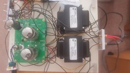
Yellow from OPT is connected to the screw terminal on the board, and black to the speaker binding post as per tubelabs diagram. When I connect it in reverse I get distortion and squeeling. (Possitive feedback).
I have attached a photo please excuse the mess, what I would like to do is add another speaker post on each channel to connect the 4 ohm tap too ( blue wire ), so that I can connect 4 ohm speakers in the future. Is this ok? Is it safe to do this without damaging the OPT. Will it work but just mean that on the 4 ohm tap c.f. won't work.
Cheers
Attachments
Last edited:
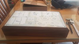
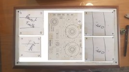
More pictures. I spent sometime mocking up the top plate today with paper cut outs. This looks.like the best solution to me. The circles around The power valve sockets are 55mm diameter my kt88's are only 51mm so I think this allows ample space for tube replacement or even larger tubes etc. The only issue with this solution Is that I would have to lengthen the OPT wires. The cathode resistor switch would need to be on The rear panel also and so would the input selector switch, the other option is mounting the Suplimental cap inside and putting the switches it's place.
Traffos would be fixed to the top panel and the circuit board mounted on the base panel with stand offs or nuts and bolts of the right length.
Any thoughts or suggestions anyone.
Cheers
MATT
Traffos would be fixed to the top panel and the circuit board mounted on the base panel with stand offs or nuts and bolts of the right length.
Any thoughts or suggestions anyone.
Cheers
MATT
Attachments
Last edited:
Matt,
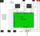
If you look at the PCB layout, you will notice that the left side has all the power connections. It is better if can place the choke and the power transformer to the left side, where your 2 x OPT is now. All the power wires can remain on one side that way.
If you could place the OPTs right at the back of the PCB, then connection wires between PCB and OPT could have been kept shortest. However, given the size of your iron, would that be possible?
If not, you can try placing OPTs to the right side of the PCB on the chassis - this way you avoid crossing of power supply wiring and OPT wiring.
Hope this helps.
OldHector,
Are you suggesting something like the attached layout?
The aesthetic changes a bit with placing the PCB in that manner, as the power tubes go in line from front to back, vs side by side. Probably will look quite nice with the KT88s that Matt is planning to use.
If all the signal wiring is kept to one side and the power wiring on the other, there should not be any potential issues with hum.
Matt,
I did not wire my SSE with CFB, hence not well versed in the connections. Will try to look it up. In the meantime it will be great if the more knowledgeable folks chime in with their inputs on your wiring scheme.
Attachments
Last edited:
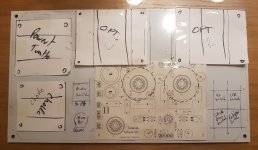
Not bad, how about this though too (attached) on zman's suggestion. This allows switching and pot too, also valves would be on display in my room. It is a tight fit but I think that there would still be enough room behind the valves for rolling or possibly larger tubes. Would have to think about fitting the OPT to the top plate and not shorting resistors etc. Maybe counter sunk holes underneath and acorn nuts on top or something.
Cheers Matt.
Cheers Matt.
Attachments
Last edited:
- Status
- This old topic is closed. If you want to reopen this topic, contact a moderator using the "Report Post" button.
- Home
- More Vendors...
- Tubelab
- Matts Tubelab SEE