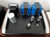
I like the term "chuffing heavy". I call my sse the "hernia amp". I just had a suggestion for an enclosure. I used a "PESANTE 4U" from diyaudiostore.com. I got the optional bottom plate and all vent top cover. It has worked great for me. There is plenty of room for transformers and chokes. It does not flex at all from all the weight of the said transformers etc. They come from italy so shipping should be cheaper for you. The valves are totally enclosed. Some may not like that idea but it made my wife happy. She was not comfortable with hot parts hanging out in the breeze. I find I fiddle less with rolling tubes and just turn it on and listen to the music.
That was the diagram I used and I have triple checked against it and my wiring looked ok to me.
When you say " centre wire " is that the red and orange wires on the diagram?
Are the pots directional? Could I of soldered it in upside down compared to the Tubelab diagram?
Thanks
Matt
Yes, if you wire it upside down, it won't work. (There is a note on the diagram that says "top view", so it's confusing.)
Yes, the red and the orange wires on the tubelab diaqram go to the center on the rca jack.
Good luck.
For a pot, the center is the wiper, which would be the output of it, which would need to go to the input of your amp.
Looking at the pot from the front, left pin should be the RCA input into the amp, and right should be ground.
When pot is turned all the way down, center/wiper is zero (or very close to zero) ohms to ground, and max ohms to RCA input.
At max volume, its the reverse, zero ohms to input and max to ground.
Hope this helps.
Really doesn't sound like a connection problem.
Randy
Cheers Randy & Colnnago
I in soldered it turned it upside down & re soldered it. It works a treat.
It was upside down.
Thanks both. When I mount the traffo 's does it matter if both Output transformers are invthe same orientation. I am struggling to get a layout on my hammond box that looks good and has them mounted at 90 degrees of each other. The choke and power traffo would be at 90 degrees to them both though
Matt
Output transformers can go in the same direction. I now also have a hammond power transformer on mine because of a noisy power transformer I had on there before. Unfortunately these are not ideal for countries that have 230V mains. At 240V setting it is quiet, at 230V setting it is noisy as well.
Attachments
Wired in CFB, UL & Rectifier IC's. Plus clarity cap suplimental cap. This is sounding awesome now. I am surprised that the 5ar4 glows when it is switched to solid state though. I prefer the sound of the valve rectifier I think. Just got to build it into my hammond walnut enclosure now. I might wire dual inputs too.
Matt
Matt
I am surprised that the 5ar4 glows when it is switched to solid state though
Turning off the heater voltage to the 5AR4 would involve finding a switch that can work with 400+ volts on it. Not a simple task. The 5AR4 remains in the circuit, it just gets bypassed with the silicon diodes when the switch turned on. The diodes are the easiest path, so that's where most of the current flows. If you want to test a pure silicon path, pull the 5AR4 then test the diode path.
I prefer the sound of the valve rectifier I think.
Most builders do too. The silicon path helps when you need every last milliwatt of power, and the music benefits from the extra voltage.
Thanks Tubelab. I tried without the 5ar4 in and using rectifiers all works fine. Prefer non ultralinear, rectification through the 5ar4, with CFB switched in, so far. The suplimental cap definately tightens things up too.
I wonder why the advise is to get double pole on off on switches Forv the UL and CFB. I have wired mine as in the diagram but onlyused 3 connectors on one the swiches.
Matt
I wonder why the advise is to get double pole on off on switches Forv the UL and CFB. I have wired mine as in the diagram but onlyused 3 connectors on one the swiches.
Matt
Just checked the diagram again and realised that I have only wired up my left channel to UL. I wondered why it was a DP switch. Will do this tomorrow. Need to work out off the 1628sea seen the correct polarity too. I read some where that if it is correct polarity it will get quieter when CFB is switched. Do I Need to power down to operate CFB or can I switch over when its running. Does anyone know if the1628sea is the correct polarity. There is supposedto be a table some where but I haven't found it yet.
Matt
Matt
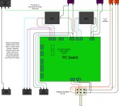
I have wired in the other channel for CFB. There is very no audible difference in volume though between either CFB switch position so I can't be sure it is wired in the correct phase. It sounds pleasant though in all settings including UL I cant detect any distortion etc.. I used the Tubelab wiring diagram below, is anyone able to confirm If the 1628sea are suitable for this wiring arrangement as I can't seem to work it out.
Thanks
Matt
Thanks
Matt
Attachments
Last edited:
I grabbed the bull by the horns and switched the c.f. switch while switched on and playing tonight. In the switch position where the blue and black wires are engaged (toggle switch right) on the diagram in the previous post the signal got louder not quieter. I have revearsed the phase by swapping the yellow and black wires over. When I switch the switch to the same position the signal now gets quieter. I just Need to understand the switch position to make sure I am 100% correct. But in think I have it right now. To be honest though it sounded ok when it was revearsed, so it is hard to have confidence.
Can anyone help please?
Thanks
MATT
Can anyone help please?
Thanks
MATT
My SSE is still connected in the basic triode setting. I still have to add the switches someday, but was happy with the sound and power the way it is. In the triode setting the opt secondary wires go straight to the speaker connections without going to the board. I noticed when you want another setting or add a switch that the opt secondary wires get switched over compared to the basic triode setting. I hope that helps a bit. I will add the switch someday, but that may take a few months.
Rob.
Rob.
Got to be honest, I agree. I wired mine in triode first and it does sound great. I am really not sure that it is worth the hassle of adding the CFB. Adding the CFB would be straight forward apart from the fact that some OPT are wound differently and the secondary's are revearsd apparently. I can't work out if my 1628sea's require the black ( common wire ) to be connected to the board or the yellow (8ohm tap) wire to be connected. I now have it so that the black wire is connected to the board. I need to establish which is correct though. I also can' t understand which switch position the cfb is engaged. In the tubelab diagram a few posts back is it the left pins of the switch and the centre pins that complete the circuit ( toggle switch to the right ) or is it the right pins ( switch to left )? I have found a previous post where this was covered but the photos and drawings have been removed from it so it still isn' t clear. From studying the diagram I think that it is switch to the right ( the left pins ) that engage the feed back. Please can someone confirm this and also confirm which of the yellow or black wire should be connected to the board for 1628sea so that I know the secondary's are connected correctly.
I would appreciate it if someone can help.
Thanks
Matt
I would appreciate it if someone can help.
Thanks
Matt
Without cathode feedback engaged, the negative lead of the cathode bypass capacitor connects directly to the ground bus on the circuit board.
When cathode feedback is enabled, best I recall the secondary of the output transformer is placed in between the NEGATIVE lead of the cathode bypass capacitor and the ground bus of the circuit board, thereby feeding some fraction of the output back into the circuit. Which secondary lead is the correct feedback lead depends entirely on the winding characteristics of the specific OPT in use.
If volume got louder, you likely had positive feedback. If it got softer, that likely was negative feedback.
I acquired some very mediocre distortion analysis equipment, and one of the interesting things I learned about myself is that I really don't hear distortion very well, unless it is pretty gross.
I can see the beneficial effect of the cathode feedback on a distortion analyzer, but I'm not sure I ever actually heard ( hear ) the effect just in causal listening. edit: I guess I need to correct this somewhat - on the universal Hammond 125X type transformers, the cathode feedback works very well, and is not subtle; you can really hear it flatten the frequency response. These are also easy to hook up, just pick an unused secondary lead that gives the desired amount of feedback.
I am not an audiophile, so take the foregoing for whatever it is worth.
Last edited:
I think I have worked this out. I hooked the amp up to my bigger speakers tonight. While playing in UL I switched the CFB switch over and hey Presto! I hear squealing and distortion. So I assume that my current set up of common to the amp board and 8ohm tap to the speakers is incorrect for the 1628sea's. I assume thst they do need to be wired in according to the diagram supplied by Tubelab, also the CFB toggle switech to the left is the position the brings this distortion on so I am assuming at the moment that switch left is cfb switch right is nil cfb. Will change it back tomorrow, fingers crossed.
Due to the weight of this amp I am also considering the switched cathode resistor mod too. I don't want to be lifting this thing any more than is necessary.
At the moment I have b+ of 445 -448v 560k resistors, so with the kt88\6550 according to tubelab simulations this is below the tubes max plate dissipation at 29w.
I also have a nos set of 6P3S-E russian tubes again at 560k resistors my plate dissipation of 27w would be below the max dissipation of 30w.
I am on the lookout for some nos EL34 too, possibly Tesla or winged C. By looking at the simulations the 680k resistors would give me a plate dissipation of 24w again this is lower than the max rating of 25w for EL34.
I have a spare on off on, dpdt switch and I was thinking of using this to switch between 3 different cathode resistors values. I have noticed that most people use a rotary switch with a selection of over 5 values. I don't understand the benefit of this though. Are there many more tube types to consider for resistor switching? If so which ones. and what values should I be considering apart from 680k & 560k.
Any possible clarification appreciated as always. Thanks
Hi Matt,
Yes, there are. A quick look shows that there are apparently a multitude o' pentodes and beam tetrodes with similar bases from which to choose, all of which would work in the SSE with a bit of work:
And of course, the usual caution about the power transformer's heater current capability applies here (be sure it's beefy enough!).
Yes, there are. A quick look shows that there are apparently a multitude o' pentodes and beam tetrodes with similar bases from which to choose, all of which would work in the SSE with a bit of work:
- 6V6
- 6L6 and its variants
- 5881
- 6550
- EL34
- KT66
- KT77
- KT88
- KT99
And of course, the usual caution about the power transformer's heater current capability applies here (be sure it's beefy enough!).
Last edited:
- Status
- This old topic is closed. If you want to reopen this topic, contact a moderator using the "Report Post" button.
- Home
- More Vendors...
- Tubelab
- Matts Tubelab SEE