I see you have made progress on this idea in the power supply forum. This is the approach I also plan to use with my 230-0-230Vac power transformers to supply my SPP EL86 build.
https://www.diyaudio.com/forums/power-supplies/304188-ps-choke-ground-leg-3.html#post6754228
I will have to experiment with the first cap value on what is a psuedo “choke input” supply to get 240 Vdc for the EL86 B+ correct. Are you aiming for 210Vdc only? Why?
You may want to stock up on Russian 6P43P-E power tubes while they are still easy to find inexpensively. (You mentioned that your PL84 tubes are all used and possibly suspect of bad behavior). The 6P43P tubes seem robust and had been used by diyAudio member artosalo at 300Vdc in 5k UL output transformers for ~23 watts output. (My point is not getting that much power out, but rather that your used power tubes might cause the screen run-away problems you experienced earlier).
artosalo’s amp design (which I plan to build) and experience is described here:
https://www.diyaudio.com/forums/tubes-valves/356550-el-cheapo-el86-triodes-2.html#post6260732
Hi Francois G,
Yes, I think I can find another 60V for the first stage, which will give a B+ of 270v or so, so much closer to the designed operating point. However, it does sound mighty fine as it is, even with aged and brown stained PL84's, liberated from an old TV and a couple of old bookshelf speakers I saved from a rubbish pile.
The reason for 210V is that the cathode is at around 16v, and I really do not want to exceed the 200v limit that us stated in the data sheets for the EL86 screen. The tubes that I had that red plated were NOS Philips Mini Watt. The other change I have made is the screen grid resistor to 1K. I saw that in other schemas, and after a few hours listening with UL transformers, I have not seen any evidence that the screen is stressed. With 100R the screen dissipation was close to the limit.
I built the amp with a customised power transformer with a 15V winding for PL84s because they still seem quite plentiful round my way. I have around 40 in my stocks, so I don't think I have too much to worry about. It was just that I am away from home, and all I had was a box of old TV rejects that I had been given over here.
Now to find a use for about 100 ECH84's!
Hi Francois G,
… it does sound mighty fine as it is, even with aged and brown stained PL84's, liberated from an old TV and a couple of old bookshelf speakers I saved from a rubbish pile.
That is good news - mighty fine! Congratulations! Perseverance paid off.
The reason for 210V is that the cathode is at around 16v, and I really do not want to exceed the 200v limit that us stated in the data sheets for the EL86 screen.
The maximum screen voltage for the EL86/PL84 tube has some ambiguity, but Philips and Mullard tubedata shows mostly U2 limit = 250Vdc. I plan to monitor screen dissipation carefully and keep it under 1.75 watts - probably what you achieved by using the 1k sceen resistors.
I checked the voltages again today, and the data for a PL84 seems to consistently be 200V
I read an explanation somewhere that the issue with PL84s is the orientation of the screen, which is not as shielded as some tubes, so is sensitive to screen current. I did see that the screen dissipation is an issue, and ultralinear is not always successful because the screen current is not regulated.
I think it is likely that the Russian tubes you plan to use have a different internal construction, and are more robust at the voltages you are aiming for.
I also have many PL84 of Philips and Mullard manufacture that I will use someday, so I’m interested to get to the bottom of the “real limit” on screen voltage. Could you link to the data you found that says the screen limit is 200V?
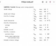
Below is a Philips data sheet excerpt for design centre data, as one example of what I found for this data. Note that max screen dissipation here is listed as 1.75 Watts, when screen voltage is 250 Vdc. I have seen another (older) Philips data sheet that listed maxima of 2.1 watts at 220Vdc.
Below is a Philips data sheet excerpt for design centre data, as one example of what I found for this data. Note that max screen dissipation here is listed as 1.75 Watts, when screen voltage is 250 Vdc. I have seen another (older) Philips data sheet that listed maxima of 2.1 watts at 220Vdc.
Attachments
Could you link to the data you found that says the screen limit is 200V?
I have some UL84's, same tube with a 45 volt 100 mA heater. The only data sheet I could find shows a 200 volt rating for G2. The GE data for the 6CW5 also states 200 volts. My guitar amp application ran 170 volts on G2 and 340 on the plate for 20 watts output, so I didn't worry about G2.
I have seen a lot of things called 6CW5 / EL86, and some of them would red plate at 10 watts of dissipation, while some old GE's would eat 225 volts on the screen and nearly 400 volts on the plate (not at the same time). Best efficiency with the old GE's was with about 190 volts on G2 and nearly 400 volts on the plate for just over 30 watts of output with nothing glowing red. This was in an SPP board with cathode bias, so the actual voltages were about 20 volts less.
Attachments
Thanks for the data sheets. Indeed, they say 200V max for screens, but the Philips sheet (from Jan 1969) below is the one I gave the excerpt of earlier; that says 250V (see page 3), or am I misunderstanding something?
My SPP build will use a 3400 Ohm OT, good for 30 watts, without UL taps. Looks like I will have to build a variable supply to dial in the best screen voltage. So, in that case should I go with a higher plate voltage than the implied by the B+ = 240V that George suggested in the manual on Tubelabs for the SPP EL86 build? Decisions, decisions.
My SPP build will use a 3400 Ohm OT, good for 30 watts, without UL taps. Looks like I will have to build a variable supply to dial in the best screen voltage. So, in that case should I go with a higher plate voltage than the implied by the B+ = 240V that George suggested in the manual on Tubelabs for the SPP EL86 build? Decisions, decisions.
Attachments
Last edited:
This one is Philips ...
Philips PL84
It stipulates a 220R screen grisd resistor and the 200V limit.
This is a Czech one with quite a lot of graphical data. It stipulates a 470R screen gris resistor and the 200V limit.
CS PL84
There is also an RCA data sheet at the same site, and that one lists data for 6CW5 and heater variants, and that one has 220V,
Is it possible that the EL86 and PL84 and not exactly equivalent (apart from the heaters)? The EL86 seems to be built to slightly more demanding standards, and sometimes one gets an EL86 with a 15V heater, and sometimes it is a PL84 built to meet the less demanding requirements.
Last edited:
Thanks for the links. These link indeed seem to say 200V on the EL86 screen is maximum. So, will the real EL86/PL84 please stand up!
For me the maximun screen voltage is more curiosity than need - no need to push power output to the limit, as 12 watt output is more than I need. Perhaps in my SPP build I will do a variable voltage screen supply, in Dave Gillespie’s EFB II fashion (see link below for implementation in Eico ST 70), that lets the regulated screen supply ride the sag on the B+ supply.
Since I have a supply of EL86 (Polam, Millard, Philips), 6CW5 (GE, Sylvania) and Reflector 6P43P-E I will do a little study of their performance in the SPP at various screen voltages, if I find time.
Error | Audiokarma Home Audio Stereo Discussion Forums
The link above seems fuzzy. Try this one and see post #15.
Eico ST-70 6550 Conversion Build | Audiokarma Home Audio Stereo Discussion Forums
Eico ST-70 6550 Conversion Build | Audiokarma Home Audio Stereo Discussion Forums
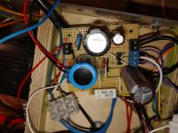
The power supply has been adapted, and the voltages are as predicted, so that is a step forward. The plate voltage on the PL84 is still 216V, and now the ECC81 B+ is 275V, the plate has increased by 30%, 175V and 95v on the two anodes. I think this has filled out the sound a bit.
The next step is connecting the feedback. I tried a 5.1K resistor in series with a 390pF for starters, similar to the standard SPP, but I ended up with a mild hum, scratchy volume control, and some sort of crackling, or oscillation. The scratchy volume control is a sign of some grid voltage, so that probably means I need to calculate the resistor value a bit more smartly.
I am fairly confident it is not the wiring of the OPT - I have experienced the howling that can result from the OPT being wired out of phase, and it is not that type of noise.
Getting closer!
Attachments
I could not get the feedback to work at all with the normal FB resistor value (5.1k). I'm a long way from understanding this. The FB resistor injects a proportion of the AC voltage from output signal to the cathode of the driver, and I would have thought that the ratio was related to the operating point of the driver tube and the output to the loudspeaker, which in my build should be more or less the same as a standard SPP.
In the end I used a 100k potentiometer and selected a point where the sound seemed nicest. This turned out to be around 43k, so I ended up fitting a 47k resistor just so I can move on to another project, and enjoy using the amp in the mean time.
The sound now does feel more precise, crisper, and the range is bit fuller, but it feels a little bit like designing using chicken entrails; it would have been nice to have been able to derive a value by simulation or calculation. Not having my oscilloscope does hamper things a bit.
I have a 490pF mica capacitor to fit at some point, but I wanted to listen to a variety of stuff first before trying that.
Hi OldHector,
I wondered how your EL86 SPP is getting along. Have you done any more fiddling with it? I’m especially curious about how you solved the feedback situation.
I would like to know, because I now have all the parts and will build EL86 SPP in the next couple months. I decided to modify a bit and plan to do “flexible” fixed bias and screen regulator according to Dave Gillespie’s EFB principles, with the same supply voltage voltage on the front-end as is used in the EL84 version of SPP (i.e. around 320V)
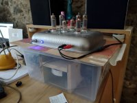
Here it is in all of its glory, and it is now used daily and I am very pleased with it. As you can see the box leaves a lot to be desired, but the high voltage stuff is safely contained, and it fits nicely next to my desk so I can listen via bluetooth during the day.
I could not get the NFB to work properly with the suggested resistor, so in the end I added a 100k pot temporarily, and since I did not have an oscilloscope here (I am working abroad for a while) I adjusted it by ear. I think it is around 40k if I remember correctly. (I can check later).
I think if I was going to start it over again I would have another solution for the power supply, although the circuit I have used does seem to work fine. Perhaps there should be a bit higher B+ than I have for the driver/splitter - I would really ave liked to match the settings in a standard SPP.
The EL86/PL84 requires a bit more drive than an EL84, so I think if I was to take another look at it I would see how to increase the drive signal. It is loud enough for my speakers and appartment, but the overall volume is less than it could be.
Interestingly, I looked at a data sheet for EL86 and came up with this one ...
EL86 frank.pocnet
... where there are figures quoted for 250V A and G2 - so I am fairly sure there are some differences between PL84 and EL86, where not all PL84s are as strong as EL86s, although they share characteristics up to 200V.
I built my version point-to-point, because I wanted the experience ad I had an SPP with EL84s as a reference. Looking at the SPP PCB, it is not too difficult to adapt it so that it satisfies both designs, assuming the operating points need to be adjusted.
Ideally:
- Seperate heater supplies for 12AT7 and output tubes. That way PL84s can be used which make for a cheap amp (apart from the OPTs).
- Split the B+ for output tubes and driver/splitter (it is just one track I think).
- I used a 1k screen grid resistor for the PL84, but that was because my OPTs were UL, and was before I had rejigged the power supply. I should perhaps look to reduce that since it could create distortion. With 200V B+ I don't think the screen dissipation is likely to be an issue now (before I had glowing screens and red plates).
- Would be interested if you have any thoughts on the driver and splitter operating points. I did simulate what I have so I could experiment with different options, but I don't think I changed anything apart fron the cathode and screen resistors on the output tubes, and the feedback one.
Attachments
That’s the best kind of amplifier! One the fits where you would like it and could be used all day, every day. Your cake pan chassis looks kind of cute!
Thanks for your nice overview and very useful suggestions of how you would do it if you were doing it over again. That will be very helpful when I start building. I forgot to mention my Za-a = 3400 Output transformers do not have a UL tap, so it it will be easier with my adjustable screen regulator to tame the screen behavior of my EL86/xL84 tubes.
I will be using George’s SPP PCB, and I think all the changes I wanted to make are easily accomplished, including your points 1&2 above. My HV supply to the front 12AT7 will be about 320Vdc. I’m planning for B+ of 250 V and Screen supply of 200 V. The output stage is run with fixed bias in my mod, so almost the entire 250V will be across anode to cathode. We shall see if that works well; if not I will adapt. If you have the LTSpice ready to through these numbers in I shall appreciate it - I will keep the file as tutorial for my learning LTSpice.
I did search and not finding, did the time become available?Since I have a supply of EL86 (Polam, Millard, Philips), 6CW5 (GE, Sylvania) and Reflector 6P43P-E I will do a little study of their performance in the SPP at various screen voltages, if I find time.
In my brain fog and not paying attention to eBay's search, instead of purchasing ECL86 valves, bought Polam EL86s.
 Running the amp in LTSpice with EL86 at 250 volts, 250 volts at the screen (not discounting cathode bias), 1k grid resistor (per this thread), Rbias of 470Ω giving a cathode bias of -23,5 volts. Mucked about with it, unable to change the bias with the bias resistor. At this point, have a total dissipation of 11,37W.
Now searching to find the ideal bias (even though the model will not change) and what bias voltage in the model provided means (set to -38 volts), thus the question.
Thanks in advance.
Thank you for you interest in my little experiment. Unfortunately I have not done the study of operating points for the EL86 tube yet.
If I understand correctly you are looking for a more optimal operating point than what you have now. If you tell us more about your amp, B+ and output transformer (impedance, UL) we might be able to give you an opinion that could be helpful. You are using the Tubelab SPP PCB?
If I understand correctly you are looking for a more optimal operating point than what you have now. If you tell us more about your amp, B+ and output transformer (impedance, UL) we might be able to give you an opinion that could be helpful. You are using the Tubelab SPP PCB?
Last edited:
- Home
- More Vendors...
- Tubelab
- Tubelab SPP with EL86/6CW5