I have just finished my 2nd SPP, this one using the EL86 variant.
After one teething problem - due to the difficulty reading the colours on those tiny 1/4 watt resistors (I am going to start to use 0.6 watt to make it easier) - I had a living, breathing amp, producing sweet music. The sound was comparable to my 6P14P (Russian EL84) one.
However after 20 minutes or so I noticed the tubes were starting to take on a orange-ish hue, the dreaded red plate.
Checking voltages, I see (with some variation between the tubes)
V(k) - 17v
V(a) - 210v
V(g1) - 0.02v
V(g2) - 211v
Voltage across the screen resistor (100 ohms) is 0.3v, so I(g2) = 3ma
Voltage across the cathode bias resistor (270 ohms) is 17v, so I(k) = 63ma
Plate voltage is (210 - 17) = 193v. Therefore dissipation is 193 * (63 - 3), which is 11.6W.
Assuming my maths is OK, and my rookie knowledge is not too lacking, then I suppose that dissipation figure is not so high, but I have read that cathode current should be restricted to 50ma.
Should I contemplate a 390 ohm bias resistor?
Out of interest - why is the bias resistor 5W? Is there a spike in voltage or current at some point?
And also, what is the benefit of having seperate resistors? Lots of PP designs using a common resistor, and a lot of the tube data assumes a single resistor in a PP setup.
I have two pairs of tubes, one is Philips NOS and the other is HQ, which looks like an old brand but I had not heard of before I bought them.
The HQ tubes are not as well balanced as the Philips ones (19.6 and 15.6 V(k)), and I suppose that is down to them not being a quality brand.
Does anyone ever fit a balancing trimmer from each of the bias resistors with the wiper going to ground?
Out of interest - why is the bias resistor 5W?
In your example with the mismatched tubes you see 1.4 watts dissipated in the cathode resistor. Common engineering practice calls for a 2X safety factor on all resistors with respect to power rating, so technically a 3 watt resistor could suffice. This board is also used with 6BQ5 / EL84 tubes which need a 5 watt resistor, so the board must accommodate 5 watt resistors. The common 5 watt white ceramic and sand resistors are cheaper than a 3 watt resistor, so the choice is easy......put a 3 watt resistor there if you want.
one resistor and one cap for a push pull amp WAS common. That was done in the days when tubes were cheap, and caps were expensive, but it is a compromise. Much of the AC currents cancel, so a smaller value cap can be used. You won't find too many modern HiFi designs with a common resistor.And also, what is the benefit of having seperate resistors? Lots of PP designs using a common resistor
Should I contemplate a 390 ohm bias resistor?
If the tubes are showing plate color you should reduce the current. Increasing the cathode resistor is the easiest way to do this. My guess is that a 330 ohm may be OK, but you might try both 330 and 390 ohm to find the best compromise between sound quality and tube life.
There are lots of different flavors of "6CW5's, and quite a bit of variability between them. I have used mostly GE 6CW5's in my SPP amps and the 270 ohm works OK. I tested some UL84's that only state "made in France" and they seem to want less current in a SPP. They were actually used in a guitar amp where they worked well with 340 volts on the plates and 170 on the screen grids. I was getting over 20 watts from them without any glow at all.
Hi George, thanks for the explanations, which make perfect sense now I can see the design rationale.
I’ll experiment with the cathode bias resistor. Hoping i’ll be lucky enough to have some candidates knocking about, otherwise it will be a long wait until the spares shop opens again on Tuesday ;-/
I’ll experiment with the cathode bias resistor. Hoping i’ll be lucky enough to have some candidates knocking about, otherwise it will be a long wait until the spares shop opens again on Tuesday ;-/
I have suspended this build because I don't think it is viable.
I have a power supply that provides a B+ of 211v, and I have OPTs that have ultralinear taps. The goal was to limit screen = plate at 200v, and run the amp in ultralinear config. However the tubes soon start to glow red in that setup, and now I think it is the screen that is overheating, and that the tube is partially running away and partially overheating due to a design limitation (screen voltage) being overstepped.
So I think there are two options from here if I retain the EL86.
1) Modify the power supply to look like The Red Light District supply, with a dedicated regulated screen supply. Then configure the setup to be pentode.
2) Reduce B+ to max 187v, which would also impact the driver and phase splitter supplies, so might necessitate some re-jigging there.
The alternative is to just put EL84's in the board, and source another power supply transformer with higher volts.
Another solution would be to find a tube that has an operating point of Vg2 = Vp = 200V (I.e a special EL86) - does anyone know a tube that has a normal specification like that?
A true GE 6CW5 will run at 200 volts in fixed bias. The spec sheet actually shows 250 volts plate, and 200 volts screen with a 3000 ohm load for 25 watts power output in fixed bias push pull class AB1.
They show an idle current of 91 mA for two tubes at 250 volts which is 11.25 watts per tube in their data sheet. These tubes eat that without issue, but not all tubes are made that tough.
I was running GE 6CW5's in my board at about 230 volts plate and screen in cathode bias mode. That puts about 210 volts across the tube. All my tubes were pulled out of dead HP audio oscillators, so they were well used when I got them.
Just had a look at the Schematic for the sansui, and they are not ultralinear.
My ones were from toroidal and were 3.5k impedance, with 43 % ultralinear taps.
I was trying to take advantage of the UL taps, but don’t think it is possible with a standard EL86.
What screen voltage did you have?
My plan is to mod the power supply and have a dedicated screen supply.
Cheers, Richard
The Antec IT200 should give you about 189v B+, if my reading of the specs is correct, which should just about be perfect for the max rating of the screen, i.e. Vg2 = Va = 170v. (This is assuming the pessimistic reading of the tube data sheets).
That could be an option for me. However, I am quite keen to investigate power supplies a bit more, and look at regulated screen supplies, since I think that opens up some avenues for some of my other ex-TV tubes.
That could be an option for me. However, I am quite keen to investigate power supplies a bit more, and look at regulated screen supplies, since I think that opens up some avenues for some of my other ex-TV tubes.
I can't remember, but I built it exactly as per George's instructions using an Antec IT200 PT. It works well, but I got an email from a member who said a IT220 worked even better?
I plan to build an EL86 amplifier and was looking for power transformers. Did the member perhaps mean Antek 1T230? I can’t find a 1T220 on the Antek website.
The one with 19,6V on the cathode resistor is dissipating almost 14W. This one could redplate, not the others.
Could it be ultrasonic oscillation?
All the tubes were NOS. I had a pair of HiQ and a pair of Philips. Although the HiQ showed the greatest range of cathode bias, it was the philips that were redplating.
From what I have read, it is the ultralinear connection that is probably prompting the behaviour. I intend to create a regulated screen supply, and try them in a pentode setup.
Hi OldHector,
Have you completed your SPP with EL86 output tubes? I was wondering how that worked out with regulated screen supply (what voltage?). What cathode current have you settled on, and what cathode resistor value? We shall appreciate an update if you could tear yourself way from the beautiful music")
Have you determined why it did not work in your previous implementation with the UL hookup?
Have you completed your SPP with EL86 output tubes? I was wondering how that worked out with regulated screen supply (what voltage?). What cathode current have you settled on, and what cathode resistor value? We shall appreciate an update if you could tear yourself way from the beautiful music
Have you determined why it did not work in your previous implementation with the UL hookup?
Last edited:
Hi Francois, no unfortunately I stopped looking at it. I had originally bought an SSE board as well, and I completed that and made a reasonable job of a permanent solution for that. That one is in permanent residence in the hifi-setup.
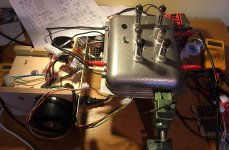
The EL86 SPP was a follow up to a PCB based SPP, and I wanted to experiment a bit. I used an old baking tin, and planned the point-to-point layout. That part of it went quite well, and I got some new metal working tools out of the experience. I also wanted to use PL84's, so I had a custom PT from Toroid with a 15V heater winding (cancelling out the cost saving of the cheaper tubes ;-/).
Now it languishes in a box, and now that I have an improved idea of what is going on under the top-plate, I need to dig it out again.
From reading other people's experiences, I think the toroid OPT's were a factor. They have a lower winding resistance, and that seems to be a factor in a UL setup with a pentode that has sensitive g2.
If I go back to it, I would probably try using a zener and pentode connection for starters. It would be helpful for me if there was an existing regulator built onto strip board, so I could compare the layout I had for my regulator. At the time I just did not have the confidence to build it and connect it in a live circuit.
I have an ongoing project to build a flexible PSU with plate, screen and a selection of heater supplies, and then I could do some meaningful testing to pin down why the tubes were red-plating like they were.
Cheers, Richard
Attachments
I am stuck working away from home, and when I started here air transport was not working, so I drove down, with some unfinished projects in the car, to try and complete and help the weekends look after themselves.
Now I am looking again at the SPP with PL84's. I have wired it back up in the same way as the picture in the previous post.
I measured the voltage drop over the 100R screen grid resistor, and on the tube I checked it was 0.9V voltage drop and (214V - 15V) on the screen, i.e. 9mA current, and hence close to 1.8W dissipation, which is just above the 1.75W in the data sheet.
I saw examples of EL86 in PP with 1K on the screen grid, so I switched to 1K 2W, and this appears to have solved the screen grid voltage and dissipation, with no signs of red plating tubes after a few hours operation.
My PL84s are from a box of second hand tubes, and I have 8 with different measured curves, but I tried to match two pairs. However the tubes are a bit of an unknown, even though they appear to be OK on the tester.
I have collected some voltage readings from tube pins. It looks to me that the ECC81 is not operating with the ideal voltage on the plate, and I noticed that gain was less than I expected.
If this is on the low side, any thoughts on how to solve it? The two halves of the tube are DC coupled, so it doesn't feel like I have many options, unless I can be creative with the power supply and have two B+ supplies. Currently it is a bespoke power trasnsformer from Toroidy, with CT 200-0-200 secondary.
Also, one of the PL84s seems to have grid current, and dissipates a lot more on the screen than the others. Is that within tolerance?
Code:
Channel R

Pin		ECC81		PL84		PL84
1		71.1(a1)	-		-
2		0(g1)		0.8(g1)		0.02(g1)
3		0.59(k1)	13.2(k)		14.6(k)
4		(h)            (h)		(h)
5		(h)            (h)		(h)
6		137(a)		-		-
7		71(g)		216(a)		215(a)
8		71.4(k)		208(g2)		214(g2)
9		(h)			-			-

Channel L

Pin		ECC81		PL84		PL84
1		73.6(a1)	-		-
2		0(g1)		0.39(g1)	0.06(g1)
3		0.50(k1)	16.6(k)		16.2(k)
4		(h)		(h)		(h)
5		(h)		(h)		(h)
6		141(a)		-		-
7		73.2(g)		215(a)		215(a)
8		73.4(k)		214(g2)		214(g2)
9 (h) - -OldHector,
Glad you are looking at your SPP EL86 again! Hope you get it fixed to your satisfaction. I already got most parts and will begin to build one soon myself, using 6P43S power tubes, so this is timely for me.
I thought of having a ~330 VDC power supply for the VA/PI 12AT7, because I reason that George probably optimized it for the EL84 build with that B+ on the front end. Perhaps George would comment on this idea.
A possibility you might consider is to reduce the 1k5 resistor before the 47uF cap on the front end, to increase the the voltage on the 12AT7 plate resistor, but I’m not sure by how much. I think a choke instead of that resistor might be a good think - higher voltage and less ripple.
It would be good to know what is the EL84 design’s voltage on the 12AT7 plate resistor, after the 1k5 resistor. Could anyone who have a working SPP EL84 be so kind as to measure the Vdc at the +B side plate resistors?
Hi Francois G,
What power transformer are you planning on using? Probably the ideal setup would be to have a voltage doubler for the higher B+, but then having a CT isn't really a benefit.
I have a choke (Triad C-14X), and was thinking I could put that on the common leg to get some benefit from it for both B+ supplies, but I think that is a non-starter, at least with the CT.
It sounds quite reasonable as it is, but I think I will need a bit of feedback, and so I need all the gain, and I do think that is reduced. Unfortunately I don't have my oscilloscope with me, so I can't make some basic measurements.
OldHector,
I have a 200VA toroidal power transformer with two 230Vac coils that I hope to use in center tap manner. I plan a choke input supply with a smallish cap after the rectifiers to adjust to get B+ at 240Vdc, as Tubelab George specified for EL86. For the 12AT7 I plan to use the 230Vac into a CRC (or CLC) supply to put ~325Vdc. I will have to play with PSUD2 and experiment.
I noticed you said that you have previously built the SPP EL84 also. Could you measure the voltage before the plate load resistors on 12AT7 sometime and report it here? I basically would like to do the 12AT7 voltage exactly as in the EL84 implementation for my EL86 build. How does the EL84 SPP sound compared to your PL84 SPP?.
When you work on your feedback circuit and component values I hope to follow closely, as I will need to do the same for my Heyboer 3400 Ohm primary output transformers.
Hi Francois G, Currently I am stuck away from home, so the SPP is not accessible.
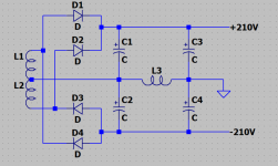
I also think that is is quite critical to find a supply at arond 300-320 so that the driver and splitter are operating as conceived. I think I ought to be able to do that with the 200-0-200 transformer, and I am trying to use LT spice to model both supplies. I am thinking along the lines of have 2 full wave rectifers, similar to the below, and using a negative rail to get the HT for the 12AT7 ....
(I'm 90% sure the choke will be worthless where it is, but I did query on the DiyAudio the PSU board )
Attachments
Last edited:
- Home
- More Vendors...
- Tubelab
- Tubelab SPP with EL86/6CW5