
Purpose of the shortening plug is to see if there is if speakers emit a noise when shortening plugs are in?
I put in a new 12at7 tube yesterday, right after I moved bias resistors.
How do I test if the chassis is grounded properly? I have a powder coated chassis. I used a toothed star washer between ground wires and chassis. Maybe I need to sand off the coating to make sure the connection is good.
Also do I need to ground each transformer?
Agreed, definetly want to get this issue resolved.
Thanks!
Last edited:
It's odd only one channel is oscillating.
An easy thing to do and eliminate - resolder all your connections on the input side of the dead channel, including around the CCS. The holes are plated through, but I still like to see solder on both sides of the board; you might have a dodgy joint somewhere.
Win W5JAG
An easy thing to do and eliminate - resolder all your connections on the input side of the dead channel, including around the CCS. The holes are plated through, but I still like to see solder on both sides of the board; you might have a dodgy joint somewhere.
Win W5JAG
I don’t have a dead channel anymore. There is audio from both channels.
Change dead to oscillating.
Change dead to oscillating.
I guess that’s where I’m lost, how do I know which channel is oscillating?
Short one input with your newly-made shorting plug, and test the other one.I guess that’s where I’m lost, how do I know which channel is oscillating?
You can check both channels for soldering problems and re-solder joints- it won't take that long.
Don't add a lot of extra solder to the joints - you don't want 'blobs' of solder causing more problems - especially under the board where they aren't visible.
Usually just touching with a flux pen and re-heating the existing solder will be enough, if the joint had enough solder the first time.
Pictures (clear ones) will help here.
Also, describing how and where you grounded the circuit (circuit ground and also to the chassis) will help.
I wouldn't worry about the transformer cases not being electrically connected to the chassis (with star washers) at this point.
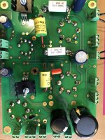
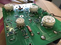
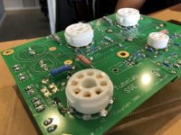
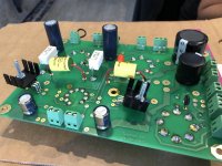
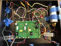
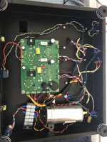
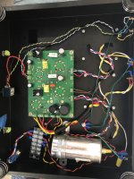
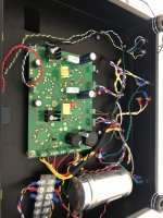
Touched up the board, here are some pictures. I also sanded down the coating on the chassis to make sure there was a good connection with the ground.
After doing this, still hearing the high pitched noise and getting an AC reading.
Have not had a chance to make the shorting rca's will try to get to them tonight.
After doing this, still hearing the high pitched noise and getting an AC reading.
Have not had a chance to make the shorting rca's will try to get to them tonight.
Attachments

Ghan-
Those pictures should help a lot.
My SSE board is still on the shelf so I can't offer any specific tips.
A few things that I would do differently, though they may have nothing to do with your oscillation problem....
-You seem to have used quite a few push-on (spade type) crimped connectors; I'd solder most of those connections.
- Same with the screw terminal block (with the clear cover)
-It's a bit difficult to see, but is the safety ground (from the AC inlet or AC power cord) connected to the chassis?
-Are the jacks (input and speaker) isolated from the chassis with shoulder washers?
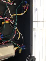
-If it were my amp, I'd shorten up the transformer wires so they run more directly to the board connectors.
You have a huge advantage in solving this problem because you are using the Tubelab board. That eliminates most of the 'wiring mistake' type of problems.
Those pictures should help a lot.
My SSE board is still on the shelf so I can't offer any specific tips.
A few things that I would do differently, though they may have nothing to do with your oscillation problem....
-You seem to have used quite a few push-on (spade type) crimped connectors; I'd solder most of those connections.
- Same with the screw terminal block (with the clear cover)
-It's a bit difficult to see, but is the safety ground (from the AC inlet or AC power cord) connected to the chassis?
-Are the jacks (input and speaker) isolated from the chassis with shoulder washers?
-If it were my amp, I'd shorten up the transformer wires so they run more directly to the board connectors.
You have a huge advantage in solving this problem because you are using the Tubelab board. That eliminates most of the 'wiring mistake' type of problems.
I did it this way to give me the ability to add CFB and UL switches in the future. If this will cause issues, I can remove, but would prefer to leave them in to make it easier to make changes.-You seem to have used quite a few push-on (spade type) crimped connectors; I'd solder most of those connections.
- Same with the screw terminal block (with the clear cover)
Yes, everything that needs to be ground is ran to a single screw, I have a wire running from that screw to the AC inlet ground. I marked the AC inlet on the pic.-It's a bit difficult to see, but is the safety ground (from the AC inlet or AC power cord) connected to the chassis?
-Are the jacks (input and speaker) isolated from the chassis with shoulder washers?
The output speakers are, but not the inputs. Sooooo I removed the inputs from the chassis and powered it up, and the high pitched noise was gone! I also measured ac / dc on the input cable it was zero. I played it for about 15 min or so, and unplugged the cable from the source and there was no loud shrill noise.
Can the solution be that simple? Is this it? Will run it longer tomorrow evening when I have more time.
-If it were my amp, I'd shorten up the transformer wires so they run more directly to the board connectors.
Was waiting to get the board in good working order before cleaning up the wires. I'll tie things down and get rid of the painters tape once all issues are resolved.
Thanks again for all of the help!!!!
Attachments
Ghan-
Well, that is progress!
Good!
Most jacks come with shoulder insulating washers, but they can be ordered separately.
Tube Amp Hardware, Chassis screws, Amp feet
Most builders nowadays try to keep 'strict control' over where the various parts of the circuit are connected to the 'common' a.k.a. 'circuit ground' and also where that 'circuit ground' connects to the chassis.
I've seen lots of older (1950s and early 60s) tube amplifiers where the chassis was used for 'everything' - signal, safety and half of the AC heater lines - and they worked OK with minimal hum. I'm pretty sure I wouldn't have the same 'luck'.
Also, now that we have quiet sources (CD and digital), our tolerance for hum and buzz is much less than in those days.
BTW, not a big deal, but as you collect more colors of hookup wire you can move toward more 'standard' (there is no compulsory standard, just habits/conventions) wiring colors. Most folks will assume that red wires are high voltage, not ground connections. I think AC power ground is usually green or green with yellow stripe, and black is commonly seen for circuit grounds ('return' in British lingo).
DIY Audio Projects - Hi-Fi Blog for DIY Audiophiles: Tube Amplifier Wiring Color Code
About the spade push on crimp connectors:
Yes, it's probably OK to leave those as-is for now.
My reasoning is a bit different...
Solder joints can be fairly easy to disconnect and re-connect if solid core wire is used and if the insulation doesn't get melted (though that can be solved with a heat shrink sleeve when re-connecting).
For good crimp connections, stranded wire is best- I'm assuming that's what you used. And, 'modern' PVC insulation is easy to melt.
Have a look at:
Best Hookup Wire? (for component internal wiring)
Between the mumbo-jumbo about 'audiophile' wire, there are some good links to teflon-insulated and other hookup wires. If you are going to pursue this hobby, it will be more fun with a supply of solid core wire in different colors.
I did it this way to give me the ability to add CFB and UL switches in the future. If this will cause issues, I can remove, but would prefer to leave them in to make it easier to make changes.
Yes, it's probably OK to leave those as-is for now.
My reasoning is a bit different...
Solder joints can be fairly easy to disconnect and re-connect if solid core wire is used and if the insulation doesn't get melted (though that can be solved with a heat shrink sleeve when re-connecting).
For good crimp connections, stranded wire is best- I'm assuming that's what you used. And, 'modern' PVC insulation is easy to melt.
Have a look at:
Best Hookup Wire? (for component internal wiring)
Between the mumbo-jumbo about 'audiophile' wire, there are some good links to teflon-insulated and other hookup wires. If you are going to pursue this hobby, it will be more fun with a supply of solid core wire in different colors.
Really appreciate all of the help. Have been running it for a few days now with no issues.
Going to add in switches for UL and CFB, when I do I'll change the wiring color.
Wiring diagram on Tubelab's site says to keep input and output wires separate, what is the recommended distance. Just trying to figure out how to space everything out.
Thanks again! Will post pictures when I get it all up and running.
I don't have an answer for that, exactly.Wiring diagram on Tubelab's site says to keep input and output wires separate, what is the recommended distance. Just trying to figure out how to space everything out.
It's not just the signal input and outputs to keep separate, it's also the AC (120 volt to the fuse and power switch and transformer, also the heater AC wiring) that I try to keep separate from the signal wiring.
Tucking wiring into the 'corners' of the chassis is useful.
Also, crossing troublesome wiring at 90 degrees rather than parallel, and keeping some of the wiring close to the metal chassis and other wiring 'up in the air' can also create separation.
A lot of those issues have been taken care of by Tubelab's good PCB layout.
And, using solid core hookup where where possible makes it easier to bend wiring into place without 'springback'. Transformer leads on new transformers seem to 'have a mind of their own', so sometimes I've used cable ties or 'P' clamps to keep them in place.
Sometimes it's not the tidy-looking wiring that's best for reducing hum and oscillations, but I try to avoid the 'rats nest' look as well. I try to remember than I can always lengthen transformer leads if necessary, at a later date.
Have been using this for a few months and it’s been working great. I recently switched my input and the hum came back. I’ve been using an rca to 3.5mm cable and no hum, when I remove the cable or plug in an rca to rca the hum is back. It hum gets louder as volume goes up. If I connect the outer ring of the input jacks to ground, hum goes away but sound is very distorted and not much volume.
When not hooked up to ground outer ring of input jacks measure a resistance of 48k. Any help would be mucin appreciated.
Thanks!
When not hooked up to ground outer ring of input jacks measure a resistance of 48k. Any help would be mucin appreciated.
Thanks!
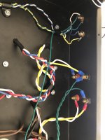
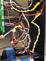
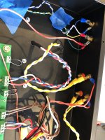
Are signal ground and signal reversed at the input RCA connectors?
Blue and white look to be signal, then they get split into green and white, and black, and then connected to signal ground.
Maybe I am looking at it wrong, but I am having trouble understanding that.
Win W5JAG
Blue and white look to be signal, then they get split into green and white, and black, and then connected to signal ground.
Maybe I am looking at it wrong, but I am having trouble understanding that.
Win W5JAG
- Status
- This old topic is closed. If you want to reopen this topic, contact a moderator using the "Report Post" button.
- Home
- More Vendors...
- Tubelab
- 1 channel fades after a few minutes of playing - SSE