On the drawing its noted that Pad 3 and Pad 4 should be connected in the 300B mode while Pad 1 and pad 4 are connected in the 45 mode. I'm not clear what is accomplished here.
In the 300B mode the center tap is open. F+ operates off a brige rectifier w/o center tap and the F- and half the bridge is at ground. I suppose C2 does nothing. The U1 regulator operates off a full wave rectifier with out a center tap.
In the 45 mode the center tap is grounded and the filament is now connected to the ungrounded bridge (with C2 keeping the F- at AC ground???) The Sharp regulator U1 is operating on a center tapped ground.
Please someone, explain how this works. Does the regulator see less voltage with a grounded center tap that with an open center tap? I can't see how the 5842 filament circuit would change; that's a good thing of course. Is there more to it?
Second question. Is the small heat sink on the U1 sharp regulator adequate for 300B service? Am I correct thinking the big external heat sink is only for the 45 service?
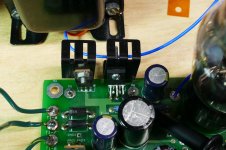
In the "45" mode the CT of the 6.3 volt winding is grounded by the jumper from pad 1 to pad 4. This makes a bipolar power supply like that found in thousands of solid state amps.
C2 is the filter cap for the negative side (the polarity is wrong on the schematic). The negative side only has 600 mA of load current, so 4700 uF is sufficient. There is excess voltage here, so ordinary 3 amp silicon diodes are used.
C1 is the filter cap for the positive side. Every millivolt of headroom is important to the regulator chip, so a Schottkey diode pair is used for low drop. 15,000 uF was the biggest electrolytic I could get in 2004 when I designed this board, so that's what is in there. Today 22,000 uF is available in the same form factor, so I will test them. The positive supply feeds an LDO filament regulator which makes 2.5 volts for the tubes. The 417A / 5842 input tubes are wired across the raw + and - supplies with a dropping resistor to get 6.3 volts on their heaters.
In the 300B mode the jumper is placed from pad 3 to pad 4. As you surmised, the heater supply for the 5842 remains unchanged, only the "ground" point moved. The transformer still has a 4 diode bridge on its full secondary, but the negative end is now grounded. As stated, C2 does nothing since it is shorted. The regulator chip now gets about 7 volts on its input instead of 3.7 volts. A jumper is placed between pad 5 and pad 6 to adjust the regulator for 5 volts out.
The size of the heatsink required has a lot to do with the airflow and ambient temperature inside the cabinet or chassis, and the line voltage that the board is running on. 300B tubes at 127 volts line voltage is worse case. Here the input to the regulator chip is slightly over it's 7 volt maximum, so the chip drops a bit over 2 volts at about 2.5 amps. It will dissipate about 5 watts and may go into thermal shutdown without some additional heat sinking. With 45's the regulator only drops 1 to 1.2 volts at 3 amps. This burns a little over 3 watts, and makes the little heat sink quite hot. My board has been running for the better part of two days with a smaller than usual heat sink on the regulator chip, 45 tubes and a variac on the input. The amp plays fine but the heat sink is too hot to touch until I get up around 126 volts, then it shuts down.
I tried both the 5 amp regulator chip and the 3 amp chip and the results are identical. See the "TSE must die" thread for more details.
Attachments
- Status
- This old topic is closed. If you want to reopen this topic, contact a moderator using the "Report Post" button.