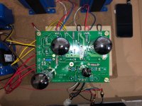
Finally put my SSE together, and was able to get sound from one side. After a few minutes, there was loud crackling noises, and one of my tubes started to really glow much brighter than the others. After powering off, I noticed that the Capacitor in c12 popped and there was liquid draining from it.
Some pictures attached, any help would be appreciated.
Thanks!
Some pictures attached, any help would be appreciated.
Thanks!
Attachments
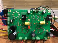
As a follow, I put in a new cap at c12, and also checked all my other solder joints.
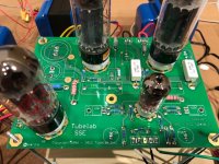
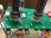
Went through ty Bower's checkout, but I'm not getting any readings, even when powered off. Everything shows up as 1. Have not fired it up again until I understand why I'm not getting any reading here.
Saw on another thread the issue might be d3 d4 tr1, however, I have put in the parts per this thread: Starting a SSE build
Thanks!
If C12 got hot enough to blow and the associated output tube got red hot, then something caused an overly excessive current to flow. There are only a few tings that could do this:
The tube was defective. An internal short between the elements inside the tube could cause this kind of failure. The tube could have been defective when made, or been damaged by rough handling.
The original C12 was defective, counterfeit, or damaged during installation. There is a light colored area in the photos on both caps that may just be a stray light reflection into the camera, or soldering iron heat touching the cap.
Backwards installation is possible, but they do look correct in the picture.
The 560 ohm resistor could be wrong, defective, or poorly soldered. Measure it to verify 560 ohms. Put one meter lead on a ground location (T1-RED-YEl) or middle of the input connector. Put the other lead into the hole on either side of the keyway on the output tube socket with the tube removed. You should read about 560 ohms, and both tubes should be the same.
C11 could be defective, leaking plate voltage from the 12AT7 into the EL34 grid circuit. This has been seen before with other high end caps. It resulted in a blown cap and output tube. It's rare, but happens.
Wrong, missing, or defective parts here can not cause tube and cap meltdown.
I.m not familiar with that procedure, but I assume that you are measuring resistance? If so the amp MUST be turned off and unplugged from any power source. Post a link and I'll look at it.
First off put your meter in the mode that you are reading "1" then tough it's two leads together, it should read something close to zero. If not your meter isn't working right, or you are doing something wrong. If you get near zero, then touch the leads to the wires on one of the 2 white resistors, if the meter stays on "1" then turn the range switch to a higher resistance range. Try them all until you see something close to 560. Then test the other white resistor, and verify the complete path to the tube socket as explained above.
Put your meter on its highest resistance range and touch the probes to each end of the yellow coupling caps, or their solder pads. The meter will change numbers for a few seconds then stabilize somewhere above 100,000 ohms. Swap the leads and repeat. Verify that both caps are the same and read above 100,000 in at least one direction.
Remember the amp MUST be off and disconnected from power for at least 5 minutes before making any resistance measurements. Attempting to measure resistance in a live amp can blow stuff up, most likely the meter.
The tube was defective. An internal short between the elements inside the tube could cause this kind of failure. The tube could have been defective when made, or been damaged by rough handling.
The original C12 was defective, counterfeit, or damaged during installation. There is a light colored area in the photos on both caps that may just be a stray light reflection into the camera, or soldering iron heat touching the cap.
Backwards installation is possible, but they do look correct in the picture.
The 560 ohm resistor could be wrong, defective, or poorly soldered. Measure it to verify 560 ohms. Put one meter lead on a ground location (T1-RED-YEl) or middle of the input connector. Put the other lead into the hole on either side of the keyway on the output tube socket with the tube removed. You should read about 560 ohms, and both tubes should be the same.
C11 could be defective, leaking plate voltage from the 12AT7 into the EL34 grid circuit. This has been seen before with other high end caps. It resulted in a blown cap and output tube. It's rare, but happens.
Saw on another thread the issue might be d3 d4 tr1,
Wrong, missing, or defective parts here can not cause tube and cap meltdown.
Went through ty Bower's checkout, but I'm not getting any readings, even when powered off. Everything shows up as 1.
I.m not familiar with that procedure, but I assume that you are measuring resistance? If so the amp MUST be turned off and unplugged from any power source. Post a link and I'll look at it.
First off put your meter in the mode that you are reading "1" then tough it's two leads together, it should read something close to zero. If not your meter isn't working right, or you are doing something wrong. If you get near zero, then touch the leads to the wires on one of the 2 white resistors, if the meter stays on "1" then turn the range switch to a higher resistance range. Try them all until you see something close to 560. Then test the other white resistor, and verify the complete path to the tube socket as explained above.
Put your meter on its highest resistance range and touch the probes to each end of the yellow coupling caps, or their solder pads. The meter will change numbers for a few seconds then stabilize somewhere above 100,000 ohms. Swap the leads and repeat. Verify that both caps are the same and read above 100,000 in at least one direction.
Remember the amp MUST be off and disconnected from power for at least 5 minutes before making any resistance measurements. Attempting to measure resistance in a live amp can blow stuff up, most likely the meter.
Thanks, I was actually able to get it up and running this afternoon. It's been on for a few hours now and no issues.
This is the checkout procedure I followed: https://www.diyaudio.com/forums/tubelab/158719-simple-se-checkout-dummies.html#post2051548
Not sure if this was the issue, but I read in another post that FREDS (D1 and D2) could be could be bad. After removing them, I was able to go through the checkout procedure above with relative ease.
Few follow up questions:
On 12at7 pins 4 and 5, I'm reading 4.7, is this to low, should it be closer to 6.3? Same thing with pin 2 of the power tubes, reading 4.7. On pin 2 of the rectifier tube I'm reading 6.4 and pin 4 reading 170v. Are these OK? They differ from the checkout, but if these are good, will start add in my Supplemental Cap and wire for UL and CFB, and move it into an enclosure.
I'm running EDCOR CXSE25-5K for my OPT's, XPWR035 for power and CXC125-10H-200mA for my choke.
Loving the amp so far, sounds incredible.
Thanks!
- Status
- This old topic is closed. If you want to reopen this topic, contact a moderator using the "Report Post" button.
- Home
- More Vendors...
- Tubelab
- Help with SSE!