The amp is running. Sounds super with Altecs. No noise or hum with ears stuck into the horns. Surprisingly R6 is hotter than R36. IC3, Q1/2 and IC1/2 are just fine.
Edcor CXSE25 | 310-0-310v | 7H /60R /200ma
B+ - 350v
B- - 148v
5AR4 - 5.1v
300B - 70v| 5.3v | 60ma
5842 - 178v | 6.14v
Thanks George.
Edcor CXSE25 | 310-0-310v | 7H /60R /200ma
B+ - 350v
B- - 148v
5AR4 - 5.1v
300B - 70v| 5.3v | 60ma
5842 - 178v | 6.14v
Thanks George.
Hi guys, I need a little help from you,
I started building my amplifier on 45 tubes, I noticed that many people started building amplifiers on tubes 2a3 and 300v, I still want to build on 45 tubes.
There is a question about the power transformer and I am faced with a choice:
HAMMOND 6K56VG i have it
Hammond P-T270FX?
Edcor xpwr 131?
Output transformers:
One Electron UBT-2?
Electra Print BE5KB?
What transformers do you think are worthy of attention and simplicity in setting up the amplifier, if, of course, you can call this project simple, in my opinion, not everything is so simple for an ordinary guy like me.
Thanks in advance guys.
Might be worth giving this a complete read. Its got the info to make a choice.
Tubes and Applications | Tubelab
Tubes and Applications | Tubelab
I didn't red your message, bought the meters and tried them.
Dumb enough to use 5V to power the meter from 5V power tranformer wires.
Clamp other two wires to R29, ON and.....luckily only 5AR4 arcing and fuse blown.
Dumb enough to try again this time using a little thing that transforms 220V AC to 5V DC , just to have an external and separated power.
JZK(R) 2 pcs HLK-PM01 AC DC 220V a 5V Paso Abajo Fuente de alimentacion Modulo Aislado Fuente de alimentacion modulo: Amazon.es: Electronica
Again same problem, another 5AR4 out.
So meters out, new rectifier, all new tests....miraculously all seem working well.
So now :
1) George I'll wait your input and make no new experiments, or use the expensive ones (Murata) like in this post :
https://www.diyaudio.com/forums/tubelab/363016-tubelab-seii-chassis.html#post6411920
2) this 5AR4 gives 430V, just to remember to lower DC I should REDUCE the polypropylene microfarad correct? Now it's 10uf, shoud for example use a 5uf
Thanks
gmonno (madrid)
I would not use any of those cheap little meters for measuring the bias in the TSE or TSE-II. The measuring leads in the case of the TSE operate at B+ potential. That puts nearly 400 volts on the meter leads. I doubt that any of these little meters were intended to work under this condition and are likely to die a quick and possibly dangerous death.
Unless the meter is specified to with 400 volts or more between it's input and power supply leads, I would not use it.
The only solution here is to use a floating power source that can also be elevated to 400 volts to run the meters. This can be made with a rectifier and cap on a small 6.3 volt filament transformer, but don't try this unless you know what you are doing.
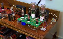
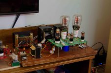
First DIY tube build - still bare, works fine and sounds superb. Runs between 360 and 370v ~ 67-70ma. I've built a test board for easy measurement on the right side.
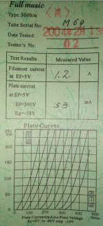
Had a question, the tube test sheet shows plate V@300v and 53ma. Is that a minimum or just a result.
Had a question, the tube test sheet shows plate V@300v and 53ma. Is that a minimum or just a result.
Attachments
Last edited:
It is a test result used for basic testing and tube matching.
It means that when the tube is tested with 5 volts on the filament, 300 volts on the plate, and -58 volts on the grid, it drew 53 mA of plate current.
They should have minimum and maximum plate current values to determine that a tube is good before shipping.
It means that when the tube is tested with 5 volts on the filament, 300 volts on the plate, and -58 volts on the grid, it drew 53 mA of plate current.
They should have minimum and maximum plate current values to determine that a tube is good before shipping.
First DIY tube build - still bare, works fine and sounds superb. Runs between 360 and 370v ~ 67-70ma. I've built a test board for easy measurement on the right side.
Had a question, the tube test sheet shows plate V@300v and 53ma. Is that a minimum or just a result.
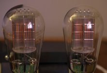
Sunil very nice tubes indeed
The datasheet is written bij engineers. The 10uF I think is minimal needed to prevent issues. This 10uF makes the bean counters happy because it is cheaper then 1000uF. But for you and me this is less a consideration (I think). And so most would choose a nice fat cap there to reduce any possible ripple a little more. Whether that is a good idea or sounds better in a filament supply is up for debate ( I don't know the answer)The datasheet calls for 10uF.
The 4700 uF cap is a carry over from the original TSE. All of these IC voltage regulators use a high gain feedback loop to compare the output voltage to a known reference and adjust it as needed.
There have been continuous debates about the audibility of these "feedback" systems, whether CC or CV is best.......
The Sharp regulator used in the original TSE had the lowest dropout voltage of any regulator I have ever tested. It however was an old design and was never updated before it went extinct.
No output impedance VS frequency specs were given for the Sharp part. The Microchip part has a graph showing a low output impedance at 100 or 120 Hz, but this rises to nearly half an ohm at 20 KHz.
The chip is driving a load of about half an ohm when feeding a pair of 2A3's so it is quite possible that any audio voltage developed across the filament in the output tubes will be present in the regulators feedback loop.
The output impedance of the regulator also rises as the regulator gets near dropout and can become nonlinear.
Testing in the original TSE did show some remnants of the audio signal across the filament supply when the amp was driven to clipping. 300B's were worse case. The big fat cap (4700 uF) reduced it to below detectability with an amplifier on my scope input.
As predicted in the data sheet the Microchip part goes crazy with no output cap, generating bursts of HF energy at a 120 Hz rate. 22 uF across the output stops the craziness. No instability was seen with 22,000 uF so I left the 4700 uF cap in place.
The data sheet cautions against using a super low ESR part, as this may add a "zero" in the feedback loop. I did not see anything unusual with a 10 uf ceramic SMD part across the 4700 uf electrolytic, but I would not put one in my amp.
As with anything like this, circuit layout and operating conditions make a difference, so feel free to experiment, but I would stay away from extremes (ceramics, less than 22 uF, or more than 22,000 uF).
Getting parts together for a TSE-II build. I have a 660v trans for the power supply and a 5H choke with 58 ohms DC resistance. Thinking that the B+ will be a bit high. Thought about using a 5U4 to get the voltage down, but prefer the slow start of a GZ34. Would putting a 5W (of yet to be determined value) resistor in series with the choke be the best way to get the B+ down? My PT has a 200ma secondary, so I think there is a bit of room to make a bit of heat.
Am I on the best path? Thanks in advance!
Am I on the best path? Thanks in advance!
Getting parts together for a TSE-II build. I have a 660v trans for the power supply and a 5H choke with 58 ohms DC resistance. Thinking that the B+ will be a bit high. Thought about using a 5U4 to get the voltage down, but prefer the slow start of a GZ34. Would putting a 5W (of yet to be determined value) resistor in series with the choke be the best way to get the B+ down? My PT has a 200ma secondary, so I think there is a bit of room to make a bit of heat.
Am I on the best path? Thanks in advance!
Adding resistor will drop the voltage. Before adding resistor, Please consider to add inrush current limiter similar like CL-60. In my experiment, it will help reduce the input main voltage 1.5 VAC for each CL-60 (my line voltage is 230 Volts 50 Hz). If you still need to drop the voltage, resistor may be added after the Choke to have LCRC filter. Please note however that if you use the same PT for Power supply and heater, adding Inrush current limiter will also drop the output voltage to Heater. I also learn from building of TSE-II that different PT will have different voltage drop under loaded conditions. I think the best way is to try first and then make adjustment from there to aim the target operating point.
I used a 10H choke and 660V trans and the B+ was not alarming. I would try setting it up and checking what B+ is before going to extremes. It seems like there are a number of variables and trying to predict exact B+ in advance is not easy. Maybe there are folks smarter than with the math that me...
I've run the TSE-II for about 200+ hours with an old RCA based GZ34. The rectifier has seen better days and wasn't NOS. I had to use a 0.22R after the secondary to get 5v for the filament.
I recently swapped in a BrimarUK GZ34 and had to change the 0.22R --> 0.1R to get 5v, everything else on the amp is the same.
All voltages etc. are the same but the 300b has dropped from 68ma to 62ma.
AC - 230v
B+ - 350v
B- - 167v
5AR4 - 5.0v
300B - 68v| 5.3v | 62ma
5842 - 175v | 6.14v
Any idea why this happens. Looks like the RCA GZ34 was pulling 4.5A (0.22R - 6.0v --> 5.0v) and the Brimar is 3.0A (0.1R - 4.7v --> 5.0v). Does that make sense ?
Last edited:
Sunil, your voltages don't make sense.
If you have to use a larger resistor to drop the transformer voltage (which doesn't change) to 5,0V with the RCA compared to the Brimar, that means the RCA is drawing a lot less heater current.
A GZ34 is supposed to draw 1,9A heater current, so for the Brimar that should be 0,19V over the 0,1ohm resistor. Thus 5,19V from the transformer.
Current differences between different GZ34's should be small, so a difference in transformer sag negligible and the dropping resistor should be the same.
What exactly are you measuring?
PS
Anything from 4,5-5,5V should be ok for a GZ34.
Last edited:
Quick question: 300B TSE mono-blocks
As covered with n other threads, I am piecing together a pair of point-to-point 300B mono-blocks using the TSE design. They’re monoblocks so that ONE can be used in my mono LP system, and because I (quite accidentally) have all the iron in stock. Plus, increased WAF and rug-rat proofing compared to the Heathkit PS rat’s nest I have now.
They’ll use a Pete Millett reg’d filament supply board (1 each block); again, have completed boards in stock. These are very similar to the TSE filament supply, except with common-mode choke on output...
My question:
Does the TSE benefit from a FUSE on the cathode leg to ground?
Given the Power Drive, I can’t imagine how you would get a run-away condition which would require a fuse, but that could be a failure of knowledge AND/OR imagination.
I looked for an answer in the PowerDrive cookbook and searched DIYaudio, but nuthin’.
Some help,’please?
If it’s merely a “can’t hurt but will probably never blow” it’s easy enuf to plan to stick one in there @ this juncture...
- Home
- More Vendors...
- Tubelab
- After a 14 year run, the TSE must DIE!