For the meter you would probably be better of with something like this with 4 wires instead of 3.
Mini Red/Blue/Yellow/Green 0.36 Inch 5 Digit Ditital LED Disply Tube Precision Digital Voltmeter Voltage Meter Panel 0.36Inch|Integrated Circuits| - AliExpress
The one you selected shares supply ground with measured ground, so I think that will not work when you measure across a resistor. I have not used a meter like this yet, I am still looking for a good option to display multiple voltages without adding a lot of meters to the amp.
Many thanks George!
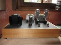
For years I have been planning to build a 2A3 power amplifier, had studied many different circuit designs but never started to build anything until George presented his TSE II.
Now it has been in operation for a few months and I am very happy with it.
Thank you George for sharing your knowledge and experience with us!
Would you think this little voltmeter would be OK to put outside the case to check bias? Any other suggestion?.....For the meter you would probably be better of with something like this with 4 wires instead of 3.
I would not use any of those cheap little meters for measuring the bias in the TSE or TSE-II. The measuring leads in the case of the TSE operate at B+ potential. That puts nearly 400 volts on the meter leads. I doubt that any of these little meters were intended to work under this condition and are likely to die a quick and possibly dangerous death.
Unless the meter is specified to with 400 volts or more between it's input and power supply leads, I would not use it.
The only solution here is to use a floating power source that can also be elevated to 400 volts to run the meters. This can be made with a rectifier and cap on a small 6.3 volt filament transformer, but don't try this unless you know what you are doing.
See this thread for a safe solution to the meter issue. It's expensive, but then so are all the parts you may blow up trying to use a cheap meter. I will still try my dumm idea when my meters arrive.
https://www.diyaudio.com/forums/tubelab/363016-tubelab-seii-chassis.html#post6411920
https://www.diyaudio.com/forums/tubelab/363016-tubelab-seii-chassis.html#post6411920
Any pictures?")
Attachments
Need some help. The rectifier secondary on the mains is showing 6v, looks like it's a mistake by the manufacturer. That's 20% higher than the required 5v. Is this safe or do I get another 5v transformer ? Forgot to add - this is with nothing hooked up, just plain testing of the transformer secondaries.
Last edited:
Hi,
Did you measure the voltage after the amplifier was in operation for a while?
You could insert a resistor in the heating wire to reduce the voltage:
6 V - 5 V = 1 V; 1 V / 0,9 A (heater current GZ34) = 1 Ohm (must be a wire wound resistor in the 3 - 4 W range).
Cheers
Peter
Did you measure the voltage after the amplifier was in operation for a while?
You could insert a resistor in the heating wire to reduce the voltage:
6 V - 5 V = 1 V; 1 V / 0,9 A (heater current GZ34) = 1 Ohm (must be a wire wound resistor in the 3 - 4 W range).
Cheers
Peter
Need some help. The rectifier secondary on the mains is showing 6v, looks like it's a mistake by the manufacturer. That's 20% higher than the required 5v. Is this safe or do I get another 5v transformer ? Forgot to add - this is with nothing hooked up, just plain testing of the transformer secondaries.
All of my filament supplies read high until i installed the tubes. Once all the tube were installed, the voltages dropped to right where they belonged.
Some basic testing with the 5AR4 and 5842.
The rectifier filament stays at 5.8v. The 300b grid is at 117v & 121v. The 5842 plate is 175v on both and filament voltage is 6.7v.
Don't have the Cat7 for RCA cabling, so the 300b has to wait. R36 & R6 get really hot. IC1/2 and Q1/2 get hot. IC3 has no heat.
The B+ & B- dropped from 411 & 163v to 403 & 148v.
B+ will drop more after you install the 300B tubes AND set the bias. This will likely also lower the 5842 filament voltage a bit. I ended up with B+ 378V and 5.8V on the 5842 filaments, had to reduce R3 to 1.5 ohm to get it up again around 6.3V.
Are you using a True RMS meter to measure the 5V AC? I have a seperate 5V transfomer where under load the voltage was 5,5V. I put a 0.22 ohm resistor in and now it is 5,1V. Will try a 0.27 ohm later.
I have everything in a re-used chassis now weighing in over 22kg. It will probably stay this way for a while. I made test points to measure voltage across R18 and R29, 5842 anode voltages and filament voltages for 300B and 5842 tubes.
It is in one of the 5V secondary leads of the transformer.

Test points PDF
To make it easy I made this test points drawing. As a beginner, its helped me during testing.
Please correct if I've missed something.
To make it easy I made this test points drawing. As a beginner, its helped me during testing.
Please correct if I've missed something.
Attachments
Last edited:
- Home
- More Vendors...
- Tubelab
- After a 14 year run, the TSE must DIE!