Would you suggest building the TSE first the way it is supposed to be built, and maybe replace the regulators later if there is a reason for it?
That is my suggestion for just about anything home built, including projects that I but with full intent on modifying them. I make sure it works as intended, then make my mods, one at a time, testing and evaluating each mod for a few days.
The reason is simple, you have all these great ideas to make something better, so you make the changes, build it all and it doesn't work. How do you troubleshoot it? Say it does work, but the sound (or other function) isn't what you expected. Is this due to the original design, or one or more of your mods. How do you know which?
I would recommend building the TSE or TSE-II as designed, then evaluating it for a few days, perhaps test assembled on a piece of scrap wood or something similar. Test, tweak and mod as desired, then build the final cabinet.
There have been two users in Europe who had a faint hum due to low line voltage. Both were fixed by adding more capacitance in parallel with C1. If this is an issue, you could always make the mods to run the output tubes on your regulators leaving the 5842's powered from the onboard supply.
Hello everyone,
I would like to know if anyone from SOCAL would be interested in these parts. I bought these parts to complete my TSE-1 but actually never had a chance to finish it.
None of these parts used more than an hour I would say.
James Audio Choke: JS-10-200S (10H 200ma)
James Audio OT: JS-6123HS (These transformers were designed with 2A3 and 300B tubes in mind, but there are many tubes that would work well with this versatile transformer since it gives you 2.5k as an option in addition to 3.5k and 5k.)
James Audio PT: JS-9612-2 (Primary impedance: 110V * 2 Secondary impedance: S1 400V-350V-0-80V-350V-400V Current: 0.35A S2 5V Current: 4A S3 6.3V-CT Current: 3A S4 5V-6.3V Current: 3A S5 5V-6.3V Current: 3A)
300B tubes: Electro harmonix gold. Matching Pair.
Step Ladder Type Attenuator Potentiometer 50K Log Stereo.
Temco Motor Run Cap: 100uf
Some Russian teflon caps.
Raytheon 584WA pre-amp tubes.
Pictures: Items for sale - Album on Imgur
Low tube plate voltage
I just got the amp installed in the chassis and did check on B+ and tube plate voltage. The B+ was down from 400 to 360 and the plate voltage was down to 3.57. I am using 300b tubes so the plate volts should be 5. They were 5 before I installed everything on the chassis. I am using the 125v tape to the Hammond 276x pt I think that was what I was using before. Any ideas why this would change?
I just got the amp installed in the chassis and did check on B+ and tube plate voltage. The B+ was down from 400 to 360 and the plate voltage was down to 3.57. I am using 300b tubes so the plate volts should be 5. They were 5 before I installed everything on the chassis. I am using the 125v tape to the Hammond 276x pt I think that was what I was using before. Any ideas why this would change?
After letting the amp run for awhile I noticed that the B+ voltage was slowly decreasing. After about 40 min it went from 354V to 327V. The plate volts stayed about 3.53 V.
Could this be a bad OP or could there be something drawing increased voltage on the board?
My TSEII does the same thing. I havent been able to figure out what was causing it
There was some discussion here earlier about using CL-90's.
If using a power transformer with dual primaries in parallel (for 120V), do you use a single CL-90 between the switch and one pair of primary wires (or between the fused L terminal and switch),
Or dual CL-90's for each primary winding? The dual CL-90's arrangement is what I've seen in the Firstwatt F5 build guides, as here:
Firstwatt F5 amplifier v3 - diyAudio Guides
Have my 300B amp up and running now for a few weeks. The detail is very good but it seems to emphasize the higher frequencies to the point of being schril. I have it running through an old Nikko SS preamp. That sounded the best out of the three I tried. Have the treble way down and the base up, but the high notes are really hot. Speakers are 96db Sonist Audio. Any suggestions where I should start to look for solutions?
Okay maybe this is obvious but is it surely the TSE and not something else like speaker positioning, the preamp, or source?
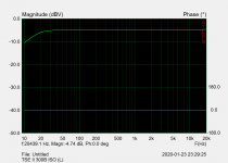
If you have a sound card analyzer, you could run a frequency response plot and see if indeed the curve of the TSE is tilted up.
Which 5842 tubes are you using? I found some subtle differences between Amperex Gold Pin, Raytheon 5842 and Western Electric 417A.
Which output transformers ?
And... what is the source?
EDIT: attached is the FR with Gold Lion PX300B tubes... pretty flat.
Attachments
Last edited:
Before this amp I was using a Jolida integrated with EL35s. Sound was very good, no shrill to it. Put the TSEII together and tried: first a custom switch box with just input switch and volume. Couldn't any volume out of it. Next tried old Easter Electric Mini Pre but that has problems I need to fix. Then used the Nikko pre and that sounded the best of the three. Yes the preamp might be part of it. I will have to hunt up another to test that out.
5842 tubes are Raytheon. Source is DVD and Vinyl.
Output transformers are Eletraprint SE 3k @ 100ma.
I can't remember what the B+ volts were or what I set bias at. I will hook up multi meters tonight and check them out.
The only rectifier tube I could get on short notice was a Groove Tube 5ar5 at the Guitar Store. I could try a better tube there.
Last edited:
At this point it would be hard to pinpoint the exact issue.
If it were me, I'd try to rule out as much variables as possible.
Starting with the source, if you have a cellphone or small portable player you can use that as your source/preamp (assuming it has volume control).
I recall that if the 300B is under-biased the sound can be shrill, so I would double check where you're at. Depending on your B+, that could be anywhere between 60mA and 90mA.
Also double check the 5842's are set at 175V.
If all of that checks out, then could be a speaker impedance mismatch. If your speaker impedance is mostly below the tap you're connected to, you'll have less than 3K at the 300B which is probably not optimal.
Total newbie here. I'm about to start the TSE-II (300b) build and had a question, wondering if you can help.
The mains trafo is a local build. It is spec'ed at 310-0-310@225mA and winding resistance is 60R (measured from 310 to 310 tap). I'm looking at between 370-380v with a choke. Will this cause problems with a GZ34 ?
How do I go about calculating the choke value? What should I do? Please help.
The mains trafo is a local build. It is spec'ed at 310-0-310@225mA and winding resistance is 60R (measured from 310 to 310 tap). I'm looking at between 370-380v with a choke. Will this cause problems with a GZ34 ?
How do I go about calculating the choke value? What should I do? Please help.
Last edited:
Can someone please help answer the trafo resistance question. Think I can work the rest.
The resistance on one half of the transformer secondary is 30R and the GZ34 spec sheet mentions ~100R (~350V). Will a resistor in series (70-100R) before the rectifier solve the problem? Is this needed /important ?
The resistance on one half of the transformer secondary is 30R and the GZ34 spec sheet mentions ~100R (~350V). Will a resistor in series (70-100R) before the rectifier solve the problem? Is this needed /important ?
- Home
- More Vendors...
- Tubelab
- After a 14 year run, the TSE must DIE!