If you haven’t done the non-standard layout in post 747 I haven’t a clue I’m afraid
Perhaps some pics would help?
I ended up sticking with the standard layout. So all the tubes are where they're supposed to be. Here's some pics (shown is the standard CLC filter iteration with auxiliary cap):
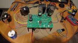
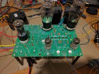
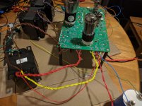
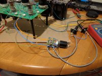
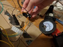
I'll read that article you sent and see if it gives me any ideas.
Did you switch out the 5842 tubes?
Try the amp without the 5842's. If the hum remains, they are not the problem.
It is possible that the filament regulator is on the edge of dropout, especially if your line voltage is on the low side. How much voltage do you have across C1, C12 or C13 (they are all in parallel).
Try the amp without the 5842's. If the hum remains, they are not the problem.
It is possible that the filament regulator is on the edge of dropout, especially if your line voltage is on the low side. How much voltage do you have across C1, C12 or C13 (they are all in parallel).
The hum is still there with the 5842's unplugged. So we can rule those out.
The voltage across C12 is 3.68V, and my line voltage is 124V AC.
Try the amp without the 5842's. If the hum remains, they are not the problem.
It is possible that the filament regulator is on the edge of dropout, especially if your line voltage is on the low side. How much voltage do you have across C1, C12 or C13 (they are all in parallel).
Hi,
I'm also experiencing hum, in dependence of the line votlage. When the line voltage is on the low side, there is hum, if the line voltage is at its max. (230 V here in Germany) there is no hum.
It seems like what George is pointing out.
In the case of dropout related issues on the filament regulator the situation can usually be improved by adding capacitance in parallel with C1, C12 or C13.
The 1N5401 diodes can be swapped for Schottky diodes if you are running 5 volts tubes. They are not in the filament circuit when using 2.5 volt tubes.
The Sharp regulator in the original TSE was the lowest dropout regulator on the planet when I designed the TSE. Unfortunately it is extinct.
When designing the TSE-II I tested everything available through distribution that had similar dropout specs in the circuit with 2A3's (worst case 5 volt 5 amp draw for two tubes) at low line voltages. The Microchip part was clean to 108 volts into a 120 volt transformer when running 2A3's. I could get that down to 105 volts with about 100,000 uF of total capacitance on the regulator input (C1). Only minimal improvements were seen above 100,000 uF. This must be a low ESR cap.
Dropout should only be an issue when low line voltage, high current demand from the regulator (2A3's) and a power transformer that delivers less than 6.3 volts under the load current drawn.
I think I figured out the source of my hum! Look at these excerpts I found:
1. Quote from a Lundahl PT page: https://www.lundahltransformers.com/wp-content/uploads/datasheets/1683.pdf --- "Output current from rectifier: 63% of above with cap. input rectifier, 95% of above with choke input rectifier."
2. Quote from the EML 5U4G page: 5U4G Emission Labs Data Sheet --- "The much more gentle L-C circuit. can load a mains transformer up to 100% of it's specified ratings, wheras C-L-C circuits can load a transformer only up to 66% (or the transformer will produce audible hum + magnetic hum field)".
According to these, the available current of my PT with a cap input rectifier is 63-66% of it's actual rating, or 130mA*0.66 at the most, which is 85.8 mA. That is not enough for the ~100mA requirement of the 45 amp. It occurred to me that I've never listened to the amp with the bias turned down on the 45's. I turned down the bias while wearing my headphones (therefore lessening the mA draw on PT), and sure enough, the hum gradually went away as the bias was turned down. So I think this means I am pulling more current than what's allowed by my transformer in a cap input rectifier PSU.
Considering that nobody complains about this kind of hum with speakers (which would have more conventional 5k8 OPTs, which would reduce hum further), I imagine this deficiency in PT amperage is not noticeable on lower sensitivity output. Confirmed this on my arya, which has a lower sensitivity. The hum was inaudible with those headphones at normal bias.
Does this explanation sound plausible? If so, it seems the solution is to simply buy a PT with a higher mA rating (maybe 160mA or higher).
Does this explanation sound plausible?
It is true that you should load a transformer somewhere between half and two-thirds of it's rating when it is running into a capacitor input filter.
Remember the filament supply is also running into a cap input filter. You made several changes in your B+ and B- supplies and these had no effect. This would indicate that the problem lies elsewhere. If you can find a big cap to add across C1, try it to see if it has any effect.
I am using a Hammond transformer with a 6 amp rating for the 6.3 volt winding. I can connect my 32 ohm headphones directly to the speaker terminals and not hear any hum, and I'm running 2A3's. Hammonds are known for producing more voltage than they are rated for.
I have used Transcendar OPT's and like them. I have never tried their power transformers and do not know how much voltage they actually deliver under load. The changing load on the B+ supply when you adjust the bias may affect the voltage on the 6.3 volt winding slightly.
Remember the filament supply is also running into a cap input filter. You made several changes in your B+ and B- supplies and these had no effect. This would indicate that the problem lies elsewhere. If you can find a big cap to add across C1, try it to see if it has any effect.
Thanks for the input. Almost all of my B+ configurations had low enough ripple to not have hum. So I figured that if there was no difference in hum from the B+ changes, it might be my PT complaining about having too much current drawn from it.
Just for the sake of trying everything, will try both a different PT (Hammond 370FX probably) as well as a cap across C1. Would this cap work: ESMH160VSN104MA80T United Chemi-Con | Mouser
In the case of dropout related issues on the filament regulator the situation can usually be improved by adding capacitance in parallel with C1, C12 or C13.
The 1N5401 diodes can be swapped for Schottky diodes if you are running 5 volts tubes. They are not in the filament circuit when using 2.5 volt tubes.
The Sharp regulator in the original TSE was the lowest dropout regulator on the planet when I designed the TSE. Unfortunately it is extinct.
When designing the TSE-II I tested everything available through distribution that had similar dropout specs in the circuit with 2A3's (worst case 5 volt 5 amp draw for two tubes) at low line voltages. The Microchip part was clean to 108 volts into a 120 volt transformer when running 2A3's. I could get that down to 105 volts with about 100,000 uF of total capacitance on the regulator input (C1). Only minimal improvements were seen above 100,000 uF. This must be a low ESR cap.
Dropout should only be an issue when low line voltage, high current demand from the regulator (2A3's) and a power transformer that delivers less than 6.3 volts under the load current drawn.
I added another capacitor of 47.000 µF at the input of the regulator.....and now my TSE-II is dead silent!
Would this cap work: ESMH160VSN104MA80T United Chemi-Con | Mouser
It should be fine.
it might be my PT complaining about having too much current drawn from it.
I have built several amplifiers including my original Lexan TSE with a transformer that was too small with good luck except for the heat produced.
When a transformer is feeding a rectifier follower by a cap input filter most of the current is drawn right at the peak of the sine wave. The TSE and TSE-II are worse in this regard because two out of three secondaries have this type of load. This can cause the transformer to exhibit higher losses at the peak current point.
An oversized transformer is good in this case. I am using a Hammond 372HX on my TSE-II because I had one. It was originally intended to power TWO SPP boards at the same time, which it did just fine, but wouldn't work with my odd packaging scheme that I made for this amp.
The 372HX works good in the TSE-II with 300B's at about 385 volts, and 2A3's at about 380 volts (way over spec). The increased filament draw is the reason for the 5 volt B+ drop.
The 370FX should do fine with 45's.
Edit, My email box tells me that AES (tubesand more.com) has "everything 10% off this week." I don't know if that's a deal or not since I haven't bought anything from them in a few years.
Last edited:
Still no volts at C11
It's me again. I had no voltage at C11. I started tracing voltages from the IC's (both channels) toward the c11 and c9. Right off I found that IC1 had 419 v at A but nothing at S & G. IC2 had 419 v at A and 211 +/- at S & G. I took an old IC from my TSE I board and tried it but got same result, but I know it is easy to short out these ICs so that one may be bad also.
I'll order a couple of new ICs (one extra) and see if that solves the no voltage problem.
OK, you have the right voltage going into IC1, but nothing coming out. The voltages are even low without the 5842 tube (post#787). There are three likely reasons for this. A bad chip, R27 or R28.
I looked at the picture that you attached in post #790 and it looks like R27 may be the wrong part. It should be 330 ohms, orange-orange-black-black-brown. Yours looks like orange-orange-black-orange-brown, which would be 330K. This would result in very low voltage coming out of the chip.
I can't tell if the colors are correct on R16 in the picture, but it should also be 330 ohms.
I recently got a good deal on a pair of Gold Lion PX300B tubes and 2 sets of 5842 tubes. So I would be interested in building a TSE. I allready built the SSE 2.5 years ago, and it is still working great.
I would like to use a pair of DHT regulators I have, each running of a separate transformer tap and also a regulator for the 6.3V 5842 heaters. Would it be possible to connect this to the pcb and not use the on board heater supply?
The power transformer I have has one 5V 3A tap, 2x 6.3V 2A taps and one 6.3V 4A tap for the heaters, all with center tap, so that is nice. The HT tap is 380-0-380V, so that is a bit high. Will have to bring that down a bit, maybe with something like a Maida regulator of different rectifier tube? I am not sure if the Gold Lion tubes also have this thermal runaway problem, the data sheet says it is good up to 450V. I will be using 5K opt's.
I am hoping someone can say if this will work with the parts I have. If someone has an old TSE board they are not using, that would probably also be good enough for what I would like to do.
Thanks,
Rob.
I have my TSE 300B at ~400V B+ and 70-90mA (there are tradeoffs for each setting)
To adjust it, you need your DMM set to measure Volts.
Since you are measuring on a 10R resistor, if your DMM reads 700mV, then your bias is set at 70mA.
Also make sure your output transformers are rated for the bias you are setting..
To adjust it, you need your DMM set to measure Volts.
Since you are measuring on a 10R resistor, if your DMM reads 700mV, then your bias is set at 70mA.
Also make sure your output transformers are rated for the bias you are setting..
I have my 300b tubes in and I get 400 B+ volts. What should my two volt meters be set to (Volts or amps) and what should the desired current be?
I run my amp at 380v and 65ma. Your b+ should drop a bit as you increase the bias
I would like to use a pair of DHT regulators I have, each running of a separate transformer tap and also a regulator for the 6.3V 5842 heaters. Would it be possible to connect this to the pcb and not use the on board heater supply?
All of this is possible, but it's a matter of how much work is involved. Assuming a TSE-II board:
I would like to use a pair of DHT regulators I have, each running of a separate transformer tap
The filament of the two output tubes are in parallel, done with two heavy traces between each of them. The trace for the positive connection is doubled up on the top and bottom side of the board to support the high current drawn by 2A3's without voltage drop. This trace would need to be cut in three places, but it would not be too hard to do.
The ground trace running to the tubes is an even bigger trace, also doubled up on top and bottom sides. It also connects to other components, so cutting it would not be a wise choice.
This would leave the negative side of both filaments connected directly to ground. I prefer this connection, but it means that tube current measurements must be made in the plate circuit. One would connect your external filament regulator's negative leads to ground, preferably directly at the tube socket pins on the board. The positive connections from each regulator would go directly to the positive filament pins on the tube socket on the bottom of the PC board. The filament regulator components would not be populated on the board.
also a regulator for the 6.3V 5842 heaters.
No board modifications are needed here. Leave out D1, D4, D5 C1, C2, C12, C13 and R3 at build time. Connect the negative side of your external 6.3 volt source to the board where D4 and D5 meet, and the positive side to board at the end of R3 closest to V1 (one of the 5842's).
You could probably drop enough B+ voltage by using a 5U4 tube and reducing the value of C4. Using a choke with a lot of DCR will help too.
An external power regulator could be used for the B+ voltage if needed. It can be connected to the board in place of or in series with the choke. The on board negative supply would still be used.
The same steps would be needed if you were using the original TSE board. It might be a little bit easier to make the PC board cuts on the old board. Both positive and ground filament connections could be easily cut as they are not doubled up so that the current measuring resistors or meters could be placed in the filament side (not B+). The old TSE board is considerably smaller and heat build up could be an issue with 300B tubes with B+ levels around of over 400 volts.
If I was to do this myself I would use a TSE-II board because it is bigger and has better thermal management, but I still have 3 of the old boards left if you choose to go this route.
Hi George,
Thanks for the detailed desciption of how to use the seperate regulators. The reason I wanted to use them is because I thought this would be best for DHT tubes. Since you built the pcb with one regulator for both 300B tubes, this would suggest that it isn't really needed to have them seperate. I am not really sure what to do, seems a waste to cut up a nice new pcb if the benefit is not going to be a lot. I do have very efficient speakers, 102 dB/1W/1m, so if there is any hum from the amp, I will definately hear it.
Would you suggest building the TSE first the way it is supposed to be built, and maybe replace the regulators later if there is a reason for it? I could allways use the regulators for another project.
Thanks,
Rob.
- Home
- More Vendors...
- Tubelab
- After a 14 year run, the TSE must DIE!