I am thinking about trying something a little different for my TSE-II 45 build, and I wanted some opinions. I am thinking about implementing a rectifier switch, so that the circuit would be optimized for either a 5AR4 or 5U4G depending on the selection of the switch. I'm thinking I can achieve this with a 270-250-0-250-270 PT and a 20H 216 ohm choke from Transcendar.
The selector switch would be 2 decks, 2 poles, 2 positions: The first deck would be for the different C4 caps needed. The connections for C4 on the PCB would go to the common terminals of the selector switch, and the two different capacitors (47uf for 5AR4 and 33uf for 5U4G) would be connected to positions 1 and 2 respectively. The second deck would have the PT HV connections on the PCB connected to the common terminals of the switch, then the two secondaries (2x 250V lines for 5AR4, and 2x 270V lines for 5U4G) would be connected to positions 1 and 2 respectively.
Modeling this with PSUD, I can get around 290V with either rectifier if I use the 270-250-0-250-270 PT and the 20H 216 ohm choke.
So, I have a few questions about this:
1. Would this even work? It looks like it would, but I have little experience and I wanted some else's opinion.
2. Are there any other modifications needed to the circuit other than switching the C4 capacitor? I've seen people talk about thermistors and current limiters, but there doesn't seem to be one consensus on how to use those with the 5U4G in this amp.
3. If this works the way I think it does, would the same concept work for a 45/2A3 switch? Maybe have OPT's with 3k and 5k primaries, and switch between them to optimize for each type of tube?
I appreciate any feedback or advice on this.
Are Remote Mounted Tubes a Problem?
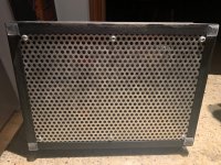
I originally built a 300B TSE-II in an enclosure (Pesante 5U from diyAudio store), and it got too hot inside so I added the quietest fan I could find, but the fan is still to loud for me. I would like to rebuild the amp in a more traditional fashion (tubes and transformers on an aluminum plate with wood base) and I was wondering if using chassis mounted tube bases and wiring back to the board is asking for trouble or if it is a nonissue. Anyone have thoughts or experience with this?
Thanks!
Attachments
I don't have a direct experience but during my online conversation with Tubelab years ago, he cited a case of one builder who did that. The issue that came up was the length of cables connecting those tubes and other components starting to affect the capacitance level too much.Anyone have thoughts or experience with this?
As for the heat build up inside, you may just need more vent openings on your amp.
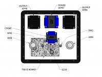
The rectifier tube could be mounted just about anywhere....but your picture shows it in the worse possible place. The rectifier tube will see several hundred volts of AC and create short charging pulses at the peaks of the line voltage sine waves that are rich in harmonic content. It should be kept away from the 5842's, their wiring, and the input wiring to avoid hum. Note that the power transformers 5 volt winding does not actually need to run to the PCB since it only goes to the rectifier tube.
The 300B's can be relocated slightly, but their wiring must be kept short. Keep them as close to the board as possible.
The 5842's will oscillate if looked at funny due to their high GM and near infinite load impedance. Many DIYers have decided that 5842's D3A's and the like are too sensitive to be wired in a PTP fashion, and successful efforts require trial and error.
It seems that you want a symmetrical look, so try this. Leave the 5842 tubes on the board, but place the large components (big caps, heat sinks...) on the back side so that the board can be located close to the top plate. Pull the board up closer to the front of the chassis and push the choke back nearly touching the power transformer so that the 5AR4 can go between the 300B's, over the board between the 300B socket areas if needed.
Note, I haven't actually measured it up for fitment yet.....just an idea.
I originally built a 300B TSE-II in an enclosure (Pesante 5U from diyAudio store), and it got too hot inside so I added the quietest fan I could find, but the fan is still to loud for me. I would like to rebuild the amp in a more traditional fashion (tubes and transformers on an aluminum plate with wood base) and I was wondering if using chassis mounted tube bases and wiring back to the board is asking for trouble or if it is a nonissue. Anyone have thoughts or experience with this?
Thanks!
Why not just build it with the standard board layout with heatsinks and caps on the bottom side of the board? You can have the sockets and tubes protruding through the top plate.
Why not just build it with the standard board layout with heatsinks and caps on the bottom side of the board? You can have the sockets and tubes protruding through the top plate.
I was thinking the same thing.
Why reinvent the wheel?
But, it is DIY...
Why not just build it with the standard board layout with heatsinks and caps on the bottom side of the board? You can have the sockets and tubes protruding through the top plate.
Thanks for asking this question. I am trying to use the board I have already built which has all the components on the top side of the board. I think I can get the existing sockets off the board by carefully cutting each pin and then desoldering them one at a time. The other reason is that I didn’t like the generic sockets I used on the original build and I want to use some higher quality machined tube sockets that don’t match the pin spacing on the board.
Thanks for asking this question. I am trying to use the board I have already built which has all the components on the top side of the board. I think I can get the existing sockets off the board by carefully cutting each pin and then desoldering them one at a time. The other reason is that I didn’t like the generic sockets I used on the original build and I want to use some higher quality machined tube sockets that don’t match the pin spacing on the board.
makes sense. I would not want to have to remove and reinstall that many components either. I think like George said your biggest issue is going to be the 5842 being mounted off the board. How about leaving them mounted on the board inside the chassis and remotely mounting the 300B and 5ar4? That should get the majority of the heat out of the chassis and prevent you from the potential oscillation issues.
Hi csample. George's idea sounds like a good plan if you still want to go that route.
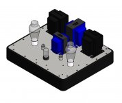
I used to embrace symmetrical layouts when I began building DIY electronics (amateur radio and audio) in earnest some 20+ years ago. As I've acquired more experience, the technical and aesthetic merits of asymmetrical layouts have become more and more apparent, and I've since become a huge fan of them. Most of this was spurred on by the Tubelab designs and some others, perhaps most notably Poindexter's Musical Machine. All of these have proven that a well-executed asymmetrical amp can be quite elegant.
Regarding heat buildup in the chassis, my experience with the TSE-II has shown that the major culprits are the power transformer (particularly the Hammond 27X-series I'm using), the heatsinked components (filament regulator, CCS chips, driver transistors) and power resistors. Paradoxically, the tubes themselves aeren't really a big contributor. Use mongo heatsinks, provide plenty of convective cooling (i.e. lots of strategically-placed holes), and you'll be fine. I'd even posit that a move away from the Pesante chassis may be a step back in terms of overall conductive dissipation, but I don't know your amp like you do.
I've attached a picture of the 2A3 TSE-II I built last year. The chassis is made of maple and aluminum, and measures 12" x 12" x 4". Despite its small size, radiant and conductive heat from the tubes is a non-issue.
Attachments
Last edited:
I originally built a 300B TSE-II in an enclosure (Pesante 5U from diyAudio store), and it got too hot inside so I added the quietest fan I could find, but the fan is still to loud for me. I would like to rebuild the amp in a more traditional fashion (tubes and transformers on an aluminum plate with wood base) and I was wondering if using chassis mounted tube bases and wiring back to the board is asking for trouble or if it is a nonissue. Anyone have thoughts or experience with this?
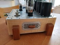
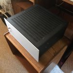
Check out the photo for my preferred build method for tube amplifiers. I normally build entirely on the aluminum top plate, and suspend the top plate off the wooden base with standoffs. This leaves a gap all the way around that allows air to flow through from a perforated bottom plate. The gap is too small for prying baby fingers, so no worries with that. Everything stays cool inside that way. No more hot box for your amp’s innards.
Attachments
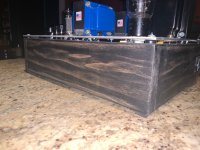

The best way to cool a tube amp silently is through convection. The photos in post #731 show how that can be done elegantly and cheaply. I have also drilled holes in top plates and base plates in an attempt to increase convected air flow through the inside of the chassis, but you will not get as much as you would doing it my way unless you drill a lot of holes. Arranging heat sinks for SS components near the perimeter gap means that heat generated by the components on these heat sinks is immediately vented out through the gap instead of staying in the chassis. For me this building method is the best example of form following function that I have used. A mostly closed box just doesn’t make sense for a tube amp that is going to be on for any length of time.
Last edited:
I usually prefer a symmetrical design and use it in many designs that do not use a tube rectifier.
My boards however are laid out with performance as the primary design criteria. The original TSE was originally intended for 45 tubes before Tubelab Inc. existed, but one of my friends stuffed 300B's in his, and that snowballed into the TSE board. It's really too small to be running 300B's on nearly 400 volts, hence the larger TSE-II when it was redesign time.
I have done something similar. The amp was built entirely on the top plate. The re were square oak wood posts in each corner of the oak base, such that the top plate sat on them, and its top was flush with the top edge of the base. Then I cut a rabbet in the top of the base with the table saw such that there was a ventilation groove all around the top plate for airflow.
It was for an SPP board that had an ugly Antek toroid and a screen regulator board hidden under the deck. That amp took EL84's where they never belonged, 30+ WPC on 425 volts of B+. It saw daily use on my PC speakers for a couple years in Florida. It's still in a box somewhere since I moved 6 years ago.
My boards however are laid out with performance as the primary design criteria. The original TSE was originally intended for 45 tubes before Tubelab Inc. existed, but one of my friends stuffed 300B's in his, and that snowballed into the TSE board. It's really too small to be running 300B's on nearly 400 volts, hence the larger TSE-II when it was redesign time.
build entirely on the aluminum top plate, and suspend the top plate off the wooden base with standoffs.
I have done something similar. The amp was built entirely on the top plate. The re were square oak wood posts in each corner of the oak base, such that the top plate sat on them, and its top was flush with the top edge of the base. Then I cut a rabbet in the top of the base with the table saw such that there was a ventilation groove all around the top plate for airflow.
It was for an SPP board that had an ugly Antek toroid and a screen regulator board hidden under the deck. That amp took EL84's where they never belonged, 30+ WPC on 425 volts of B+. It saw daily use on my PC speakers for a couple years in Florida. It's still in a box somewhere since I moved 6 years ago.
Thanks everyone for the great feedback! I had no idea about the oscillation issues with the 5842's I am glad I asked. It seems that for performance reasons it is best to keep the original layout with the tubes board mounted so that is what I will do.
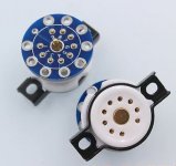
I bought a new board from George two weeks ago and I will build that with the tube sockets on top and the other components on the bottom. Can anyone suggest a high quality 9 pin socket that fits the hole spacing on the PCB? The problem I had with the generic ones (AES P/N P-ST9-217G) was the fit to the pins on the tube was very tight - I was worried that I might break the 5842 trying to push it in. Would a socket with a PCB adapter to change the pin spacing be likely to cause oscillation?
Thanks again!
Attachments
Regarding heat buildup in the chassis, my experience with the TSE-II has shown that the major culprits are the power transformer (particularly the Hammond 27X-series I'm using), the heatsinked components (filament regulator, CCS chips, driver transistors) and power resistors. Paradoxically, the tubes themselves aeren't really a big contributor. Use mongo heatsinks, provide plenty of convective cooling (i.e. lots of strategically-placed holes), and you'll be fine. I'd even posit that a move away from the Pesante chassis may be a step back in terms of overall conductive dissipation, but I don't know your amp like you do.
Hi Mr_Zenith! Your amp is beautiful! Hopefully I can build something that nice eventually. My amp had the tubes inside the chassis - which I think is why the amp got so hot. The 300B's were dissipating 37W each (80mA and 390V B+) and the area of the chassis above them was the hottest part of the chassis. It is not visible in the pictures, but the bottom of the chassis is fully perforated like the top. Maybe this fully enclosed design would have done better with lower dissipation type 45 tubes.
Attachments
was the fit to the pins on the tube was very tight
What's worse is not noticing this until I had the board completely populated. This board was a one off DIY prototype that eventually became the Tubelab SPP.
I keep some old dead tubes for loosening up the sockets before sticking any good tubes in. I also put a little WD40 on the pins of the old tubes before doing this.
I think the sockets I'm using are ST9-221G
Would a socket with a PCB adapter to change the pin spacing be likely to cause oscillation?
I'm guessing that they are probably Ok, but I have never actually tried them.
Attachments
Thanks everyone for the great feedback! I had no idea about the oscillation issues with the 5842's I am glad I asked. It seems that for performance reasons it is best to keep the original layout with the tubes board mounted so that is what I will do.
I bought a new board from George two weeks ago and I will build that with the tube sockets on top and the other components on the bottom. Can anyone suggest a high quality 9 pin socket that fits the hole spacing on the PCB? The problem I had with the generic ones (AES P/N P-ST9-217G) was the fit to the pins on the tube was very tight - I was worried that I might break the 5842 trying to push it in. Would a socket with a PCB adapter to change the pin spacing be likely to cause oscillation?
Thanks again!
I've had good luck getting sockets etc from Tube Depot. Here's what I've used and I've used their socket extenders as well, both have worked well for me.
TubeDepot.com | 9 Pin PC Mount Socket
TubeDepot.com | 9 Pin Socket Saver

This is a TSE.
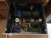
I have a TSE-II board built and tested. The next step is to design and build a more elegant chassis for it. I'm thinking of a machined top plate and a nice wooden base.
Enjoy.
If you end up doing a machined top plate there is a file, buried in this thread with the hard work done already, for the pcb layout. All I had to do was set the final dimensions and add in the cutouts for my transformers and switches.I've had good luck getting sockets etc from Tube Depot. Here's what I've used and I've used their socket extenders as well, both have worked well for me.
TubeDepot.com | 9 Pin PC Mount Socket
TubeDepot.com | 9 Pin Socket Saver View attachment 846775
This is a TSE.
I have a TSE-II board built and tested. The next step is to design and build a more elegant chassis for it. I'm thinking of a machined top plate and a nice wooden base.
Enjoy.
Hi csample, It looks like you did a heck of a job on yours, too. Beautiful job on the layout and wiring, with everything easily traceable and in its place - very professional. From the pictures it looks like you did everything I would have, and then some. Well done!
By the way, I seem to remember a post some months back from someone who wanted to build one inside a chassis like this because they had small children to protect. Was that you? I haven't had time to look back at previous posts, but if so that makes sense.
And thanks for the compliment! Honestly, the hardest part of building it was keeping it on the workbench for long enough to get something accomplished. I found myself dragging it into the living room for a "quick audition" on quite a few occasions; the problem was that "quick" usually turned out to be two or three days. It's become my favorite amp, and I have it playing in my home office for the occasional "shutdown serenade"...
By the way, I seem to remember a post some months back from someone who wanted to build one inside a chassis like this because they had small children to protect. Was that you? I haven't had time to look back at previous posts, but if so that makes sense.
And thanks for the compliment! Honestly, the hardest part of building it was keeping it on the workbench for long enough to get something accomplished. I found myself dragging it into the living room for a "quick audition" on quite a few occasions; the problem was that "quick" usually turned out to be two or three days.
It's become my favorite amp, and I have it playing in my home office for the occasional "shutdown serenade"...- Home
- More Vendors...
- Tubelab
- After a 14 year run, the TSE must DIE!