There are a couple posts regarding wiring/grounding the TSE-II, but I don't really understand. Can someone post photos or a drawing of how to properly ground the board? There was mention about removing paint from the output transformers and/or grounding the board to the chassis, but it is confusing to me.
Thanks!
Thanks!
Wiring from TSE-II board to test jacks
I'll be installing some tip jacks in the top plate of my chassis to allow adjustments without opening up the amp. I have my trim pots on the same side as the tube sockets with small holes over them in the top plate.
Please check my plans for wiring these jacks.
For the driver tubes, I'll connect a thin wire to the lead of C9 and C11 on the driver side, with the other jack connected to ground. Two pairs of tip jacks, L and R. I'll use this to adjust the voltage on the driver tubes. 175V...correct? I hope the flying lead from the capacitors doesn't turn into a little antenna looking for him.
For the 300Bs, I'll connect a couple thin wires to each side of R18 and R29. Two pairs of tip jacks, L and R. I'll use this to adjust the current through the 300Bs. Measure the voltage and divide by 10 (R18, R29 = 10 ohm). 60 to 80 mA depending on the final B+...correct?
I'll also have a pair of tip jacks across R30 to measure B+.
The idea is to have several logically place small black top jacks on the top (or maybe back) of the black chassis to allow fiddling about without opening up the amp.
This is exactly how I wired my tip Jacks on the top plates. Plus I wired at the same points to volt meters fir the 300bs and drivers I put in the front of the chassis. . Works very well for me.I'll be installing some tip jacks in the top plate of my chassis to allow adjustments without opening up the amp. I have my trim pots on the same side as the tube sockets with small holes over them in the top plate.
Please check my plans for wiring these jacks.
For the driver tubes, I'll connect a thin wire to the lead of C9 and C11 on the driver side, with the other jack connected to ground. Two pairs of tip jacks, L and R. I'll use this to adjust the voltage on the driver tubes. 175V...correct? I hope the flying lead from the capacitors doesn't turn into a little antenna looking for him.
For the 300Bs, I'll connect a couple thin wires to each side of R18 and R29. Two pairs of tip jacks, L and R. I'll use this to adjust the current through the 300Bs. Measure the voltage and divide by 10 (R18, R29 = 10 ohm). 60 to 80 mA depending on the final B+...correct?
I'll also have a pair of tip jacks across R30 to measure B+.
The idea is to have several logically place small black top jacks on the top (or maybe back) of the black chassis to allow fiddling about without opening up the amp.
Attachments

Justmikey-- where are your plans for wiring these jacks?
I meant what was described in text, I did not draw any plans.
"Originally Posted by justmikey View Post
I'll be installing some tip jacks in the top plate of my chassis to allow adjustments without opening up the amp. I have my trim pots on the same side as the tube sockets with small holes over them in the top plate.
Please check my plans for wiring these jacks."
Can you tell me what posting?
I'll be installing some tip jacks in the top plate of my chassis to allow adjustments without opening up the amp. I have my trim pots on the same side as the tube sockets with small holes over them in the top plate.
Please check my plans for wiring these jacks."
Can you tell me what posting?
I think that the wiring instructions provided for the SSE Wiring Diagrams and grounding can be implemented with the TSE-II.
Wiring Diagrams | Tubelab
Wiring Diagrams | Tubelab
Schematic vs. PCB & tubes
Hello here guy's.
While small-adjusting") my layout, before pcb are done; dubbel/trippel checking everything i came over one connection which i see on Georges layout which are not on schematic.
my layout, before pcb are done; dubbel/trippel checking everything i came over one connection which i see on Georges layout which are not on schematic.
I'am sure it dosen't matter, but i will ask anyway.
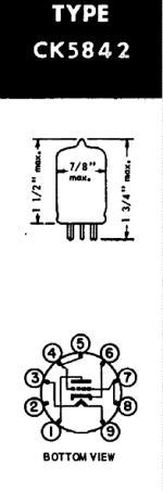
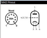
If one look carefully at V1/V2 there is trace between pin 4&5 on the board, but only on pin 4 on schematic. Looking at the pinout's of the 5842 i see that 4&5 are internal connected in the tube, same goes for pin 7&8. Still learning i donno why 7&8 never are connected on any schematic i look at at the www,
I was hoping someone could explain that?
Rgds: Jesper.
Hello here guy's.
While small-adjusting
my layout, before pcb are done; dubbel/trippel checking everything i came over one connection which i see on Georges layout which are not on schematic.I'am sure it dosen't matter, but i will ask anyway.
If one look carefully at V1/V2 there is trace between pin 4&5 on the board, but only on pin 4 on schematic. Looking at the pinout's of the 5842 i see that 4&5 are internal connected in the tube, same goes for pin 7&8. Still learning i donno why 7&8 never are connected on any schematic i look at at the www,
I was hoping someone could explain that?
Rgds: Jesper.
Attachments
The "plans" are written in the text of post 542 which is quoted below:
I'll be installing some tip jacks in the top plate of my chassis to allow adjustments without opening up the amp. I have my trim pots on the same side as the tube sockets with small holes over them in the top plate.
Please check my plans for wiring these jacks.
For the driver tubes, I'll connect a thin wire to the lead of C9 and C11 on the driver side, with the other jack connected to ground. Two pairs of tip jacks, L and R. I'll use this to adjust the voltage on the driver tubes. 175V...correct? I hope the flying lead from the capacitors doesn't turn into a little antenna looking for him.
For the 300Bs, I'll connect a couple thin wires to each side of R18 and R29. Two pairs of tip jacks, L and R. I'll use this to adjust the current through the 300Bs. Measure the voltage and divide by 10 (R18, R29 = 10 ohm). 60 to 80 mA depending on the final B+...correct?
I'll also have a pair of tip jacks across R30 to measure B+.
The idea is to have several logically place small black top jacks on the top (or maybe back) of the black chassis to allow fiddling about without opening up the amp.
5842 Grids are at pins 4,5,7 & 8.
You can choose to use any one or combination of, or all.
In the past (a different project) I have used 1 pin (whichever I chose) with a CC grid stopper as well as a ferrite bead to prevent oscillation.
I have not seen any oscillation issues with the TSEII.
You can choose to use any one or combination of, or all.
In the past (a different project) I have used 1 pin (whichever I chose) with a CC grid stopper as well as a ferrite bead to prevent oscillation.
I have not seen any oscillation issues with the TSEII.
Last edited:
Thanks Andrewbee...
So i contacted Toroidy, asked them for some custom OPT, and a mains trafo.
The answer was this
I also asked them what idle voltage is, and if several impedances was possible, and the answer is :
I asked "elobilo" from here via PM, what specs. his Toroidy is. He told me that the specs. are as follows :
>340 - 0 - 340v / 175mA
>5v / 2A
>6.3v (4A)
He told me to consider a higher voltage at 350 - 0 - 350 or 360 - 0 - 360 for higher voltage also. He also said that i should by a bigger one for running a bit cooler.
So i'am kindly asking if someone can help/confirm that the best transformers to have wound is as :
Mains:
Primary 230vac
Sec. 360 - 0 - 360
Sec. 5v 3A
Sec. 3.15 - 0 - 3.15 (5A)
Output(s):
Intended for Single Ended
Core type Toroidal
Ultralinear tap 43%
Nominal Power 40W
Nominal anode current 250mA
Frequency bandwidth (-3dB) 10 Hz - 56 kHz
Secondary Impedance 4 and 8 Ω
Primary Impedance 3,0 kΩ
Turns Ratio (Np:Ns) 27,39:1 (4Ω) , 19,36:1 (8Ω)
Primary Inductance Lp 39,5 H
Primary Leakage Inductance Lsp 10,88 mH
Total Primary DC Resistance 85,4 Ω
Effective Primary Capacitance 7,6 nF
Dimensions (standard) 115 mm (OD) x 65 mm (h), weight: 2,5 kg
Dimensions EXPO 120 mm (OD) x 80 mm (h), weight: 4,4 kg
But with 5kOhm primary impedance.
Hey... good weekend
Jesper.
So i contacted Toroidy, asked them for some custom OPT, and a mains trafo.
The answer was this
TS250VA PRI: 2x115V SEC:
> 325 - 0 – 325V (250mA)
> 5V (3A)
> 3,15 - 0 - 3,15V (5A)
Audio Grade version (potted inside) – 107,30 EUR / pc
Supreme version (fully potted in the stainless steel box) – 165,80 EUR / pc
Custom made TTG-KT88SE modified to 5kOhm imput impedance:
Audio Grade version (potted inside) – 105,60 EUR / pc
Supreme version (fully potted in the stainless steel box) – 154,20 EUR / pc
I also asked them what idle voltage is, and if several impedances was possible, and the answer is :
Total regulation of the 250VA transformer is ~12-15% and it’s distributed proportionally depending on the power generated in the winding.
Unfortuantely is it not possible to have the output transformers with both 5kOhm and 3,5kOhm primaries.
I asked "elobilo" from here via PM, what specs. his Toroidy is. He told me that the specs. are as follows :
>340 - 0 - 340v / 175mA
>5v / 2A
>6.3v (4A)
He told me to consider a higher voltage at 350 - 0 - 350 or 360 - 0 - 360 for higher voltage also. He also said that i should by a bigger one for running a bit cooler.
So i'am kindly asking if someone can help/confirm that the best transformers to have wound is as :
Mains:
Primary 230vac
Sec. 360 - 0 - 360
Sec. 5v 3A
Sec. 3.15 - 0 - 3.15 (5A)
Output(s):
Intended for Single Ended
Core type Toroidal
Ultralinear tap 43%
Nominal Power 40W
Nominal anode current 250mA
Frequency bandwidth (-3dB) 10 Hz - 56 kHz
Secondary Impedance 4 and 8 Ω
Primary Impedance 3,0 kΩ
Turns Ratio (Np:Ns) 27,39:1 (4Ω) , 19,36:1 (8Ω)
Primary Inductance Lp 39,5 H
Primary Leakage Inductance Lsp 10,88 mH
Total Primary DC Resistance 85,4 Ω
Effective Primary Capacitance 7,6 nF
Dimensions (standard) 115 mm (OD) x 65 mm (h), weight: 2,5 kg
Dimensions EXPO 120 mm (OD) x 80 mm (h), weight: 4,4 kg
But with 5kOhm primary impedance.
Hey... good weekend
Jesper.
Be careful with your secondary HV voltage rating. The current looks fine (250mA).
I'm using a Hammond 372JX which IIRC is a 600Vct secondary and I am running 350 B+ @50mA
With a 720Vct secondary you are going to end up well over 400V which a lot (most) 300B's will not tolerate. If you try running the 300B's at high current then you start getting into dissipation issues.
IMO opinion choose an operating point and design for it.
You can adjust the size of the first capacitor in the B+ power supply (C4?) to adjust the voltage a little.
Perhaps you could ask for multiple secondaries since you are going for a custom wind.
Be careful with your secondary HV voltage rating. The current looks fine (250mA).
I'm using a Hammond 372JX which IIRC is a 600Vct secondary and I am running 350 B+ @50mA
With a 720Vct secondary you are going to end up well over 400V which a lot (most) 300B's will not tolerate. If you try running the 300B's at high current then you start getting into dissipation issues.
IMO opinion choose an operating point and design for it.
You can adjust the size of the first capacitor in the B+ power supply (C4?) to adjust the voltage a little.
Perhaps you could ask for multiple secondaries since you are going for a custom wind.
Hi...
Yes i see that the voltage would be higher as good!
But elobilo told me, that with his 340 - 0 - 340 @ 175mA is ending up with 378v, but that could ofcause also be that the lower VA torrid he use are getting draged down? I Donno?
But asking them for say secondarys at :
300 - 0 - 300 / 330 - 0 - 330 / & maybe 350 - 0 - 350... Think it's not very expensive through. - Could be nice to have anyway, also gives me the possibility to tryout 45's tube maybee at some time?
I really have to think this through, but it's no rush i think i will order them at the end of the year first, so giving me some time to get it right thanks.
Jesper.
- Home
- More Vendors...
- Tubelab
- After a 14 year run, the TSE must DIE!