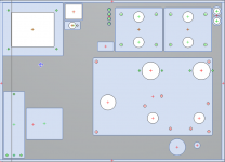
I have 2 options for layout and would appreciate feedback.
-Dimensions are 16"x11.5"
-This is for a headphone amplifier. Volume and headphone jack are in the front right.
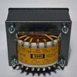
-Power transformer is similar to the one pictured.
-Bottom leftis tomchr's 21st Maida Regulator which has proven to be effective in eliminating hum with my setup.
-Top plate will sit on top (not permanently screwed) on wooden base so prefer all parts on top plate.
Generally, I prefer the non-A option. Centers of all transformers are aligned on-top and (unless I'm mistaken), the center axis of the PT is not "pointing" at the tubes or OPT's. The only thing I dislike about this is the position of the IEC inlet.
Option A solves puts the IEC inlet in a better position, but I'm not sure if the rotation of the PT is now an issue. Although, in this layout the PT is even further away from the OPT's.
Thoughts?
-Dimensions are 16"x11.5"
-This is for a headphone amplifier. Volume and headphone jack are in the front right.
-Power transformer is similar to the one pictured.
-Bottom leftis tomchr's 21st Maida Regulator which has proven to be effective in eliminating hum with my setup.
-Top plate will sit on top (not permanently screwed) on wooden base so prefer all parts on top plate.
Generally, I prefer the non-A option. Centers of all transformers are aligned on-top and (unless I'm mistaken), the center axis of the PT is not "pointing" at the tubes or OPT's. The only thing I dislike about this is the position of the IEC inlet.
Option A solves puts the IEC inlet in a better position, but I'm not sure if the rotation of the PT is now an issue. Although, in this layout the PT is even further away from the OPT's.
Thoughts?
Attachments
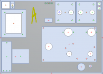
Where are the input jacks?
If I had it to do over again, I would definitely put everything in the top panel like you're planning.
I'd also probably put the headphone jack by the output tx's. I know that means you need a longer headphone cable, but all my cables are long enough so it would work fine.
I have no idea about tx orientations. I used the non A orientation fwiw.
The input jacks on in the top right.
I was planning on routing the input wiring along the exterior edge of the panel.
I like the aesthetics of the jack in the front.
For the OPT, I was planning on connecting them to a terminal strip (euro style or "classic" solder terminal), and from there another wire to the jack.
Why do you prefer it by the OPT? I think that specific wiring isn't overly sensitive to position.
I'd put the output jacks by the opt because that's what it connects to, so shorter wires.
For the same reason, I'd put the input jacks in the front, by the volume pot.
But this may make you need longer headphone wires and interconnects to the source or preamp, so as a system might not matter.
I also do things non standard at times, and I know the headphone jack in back and inputs in front is backwards from most commercial products but I don't really care about that.
Randy
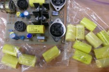
I make the BOM in an old version of Excel then convert to PDF. Here is the XLS version.
The forum does not allow uploading a file with the extension .xls I simply changed the extension to .txt, so you must change it back to .xls
If it helps the forum members and George is ok with it, I can make a shopping cart on Mouser and share the link - then ordering all the parts becomes a matter of a few clicks.
George,
Can you please clarify the following:
- R2 SEE NOTE #2 - cannot find the NOTE
- For coupling caps you are recommending 0.1 uF and not 0.22 uF as in the earlier parts list?
Per the BOM notes:
"2) R2 MUST be 100 ohms for 45’s and 2A3 tubes to provide 2.5 volts. R2 MUST be 300 ohms for 300B’s to provide 5 volts. Measure the filament voltage BEFORE installing any tubes!"
Regarding coupling caps, I can't remember where but it stated that 0.1uF is min. value to avoid bass roll off, and that 0.22uf-0.47uf are good values.
-Top plate will sit on top (not permanently screwed) on wooden base so prefer all parts on top plate.
You want the top plate secured to the rest of the chassis. Just allowing gravity to do the job will end in disaster, tears, and broken toes when you go to move the amp and forget that the top isn't tied down.
Tom
Zman are you talking about Mouser's Shared Project? If so, I think that works really well. A project I am building used that and it was "one click" ordering. You can also unselect any item you don't want to purchase. Although I believe George has said he wasn't able to get all of the parts for the TSE II from the same place but you could get a lot of them.
Ken
Ken
R2 sets the filament voltage for the output tubes and one would be wise to measure and verify correct voltage before installing any tubes.....several years ago I had to learn the hard way that 45's don't live long on 5 volts.
The TSE-II use 1 meg resistors on the gates of the mosfets VS the 470K resistors used in the original TSE. This allows the use of smaller coupling caps in the TSE-II to get the same low frequency corner. A 1 meg resistor with a 0.1uF cap should result in a 3dB point of 10 Hz. Going to a larger cap is not necessary and could result in problems with OPT saturation if the rest of the system has no low frequency poles. My old solid state system in the 1980's would make the woofer cones move in and out when playing a slightly warped record. If the plate current varies in the output tubes in step with the warp in a record, you need a higher corner frequency. A true RIAA phono stage should take this out, but not all have the low frequency pole.
Fine by me.
I tried to choose all the small parts such that Mouser and Digikey both have them, or include compatible parts from both vendors. Of course neither of these places have tube sockets or tubes. I often get them from AES, or their distributor CE distribution, who is "wholesale to the trade" only.
it stated that 0.1uF is min. value to avoid bass roll off, and that 0.22uf-0.47uf are good values.
The TSE-II use 1 meg resistors on the gates of the mosfets VS the 470K resistors used in the original TSE. This allows the use of smaller coupling caps in the TSE-II to get the same low frequency corner. A 1 meg resistor with a 0.1uF cap should result in a 3dB point of 10 Hz. Going to a larger cap is not necessary and could result in problems with OPT saturation if the rest of the system has no low frequency poles. My old solid state system in the 1980's would make the woofer cones move in and out when playing a slightly warped record. If the plate current varies in the output tubes in step with the warp in a record, you need a higher corner frequency. A true RIAA phono stage should take this out, but not all have the low frequency pole.
and George is ok with it, I can make a shopping cart on Mouser and share the link
Fine by me.
George has said he wasn't able to get all of the parts for the TSE II from the same place
I tried to choose all the small parts such that Mouser and Digikey both have them, or include compatible parts from both vendors. Of course neither of these places have tube sockets or tubes. I often get them from AES, or their distributor CE distribution, who is "wholesale to the trade" only.
George,
Seems like I confused the "or higher" part in the BOM.
"R9/R11: .1uF 450V (or higher) tubular capacitor"
Cross-referencing older threads, I assumed "or higher" meant .22 or .47 but seems like you meant higher voltage rating.
Given that, I installed .22uF caps. Any concerns there worth replacing for .1uF caps ?
Per the BOM notes:
"2) R2 MUST be 100 ohms for 45’s and 2A3 tubes to provide 2.5 volts. R2 MUST be 300 ohms for 300B’s to provide 5 volts. Measure the filament voltage BEFORE installing any tubes!"
This part needs to be how many watts?
He did. As George explained, mucking about with the capacitance value for the coupling caps can wreak havoc with the frequency response and/or cause system instability (bad). Their voltage rating is 450 V minimum to prevent breakdown of the dielectric (really bad). Regardless, the specified 0.1 uf cap was chosen carefully and will yield plenty of bass.I assumed "or higher" meant .22 or .47 but seems like you meant higher voltage rating.
")
I believe I used a 1/2 watt resistor because it's what I had on hand, but you could likely get away with 1/4 watt. It creates a voltage divider to set the output for the regulator, so it doesn't see any real current.This part needs to be how many watts?
Last edited:
you meant higher voltage rating.
Yes. The cap can see B+ voltage on the driver end before the tubes are warmed up, and bias voltage on the other end which can be 80 volts or so on a 2A3 or 300B that is run at a high B+ voltage. A cap rated for 450 volts is the minimum I would use here unless you know that your amp does not go higher. A 45 amp running about 300 volts could use a 400 volt cap, but an amp running one of those pricey mega 300B's on 450+ volts probably should use a 600 volt cap.
If a .22 cap works fine in your application, use it. One of my old TSE's had 1uF caps in it because I had a box full of 1uF "Wonder Caps" (remember that fad from the late 80's). They worked fine, and are still in the amp.
This part needs to be how many watts?
a 1/4 watt resistor is fine. It sees less than 50 milliwatts.
If a .22 cap works fine in your application, use it.
Which measurement can I perform with an oscilloscope or sound card that would indicate whether the larger cap is an issue or not ?
I'm not an authority on oscilloscope measurements by any means, so I'll leave that to others who know better. But I will say that sometimes the effects of coupling caps can be obvious. I once tested a breadboarded amp about 10 years back that sounded "funny". When I removed the speaker grilles I could see one of the woofer cones was pumping in and out at about 1/2 Hz. The oscillation disappeared when the 1 uF coupling caps (the schematic I was following called for them) were replaced with 0.22 caps.
George's remarks are absolutely correct though, and my apologies if I sounded like I was speaking in absolutes or talking out of turn. I was replying via my phone from the cab of a parked truck on a 90 °F day.
George's remarks are absolutely correct though, and my apologies if I sounded like I was speaking in absolutes or talking out of turn. I was replying via my phone from the cab of a parked truck on a 90 °F day.
I've never heard of them as I was in my 20's then and far too busy being young and stupid. Apparently they're still available, though the selection is severely limited (I suspect they're likely the last remaining NOS). Now that I'm old and stupid, I find that orange drops suit me just fine. Usually.(remember that fad from the late 80's)
Based on bill of materials shared by Tubelab in post 440 of this thread, here you go with the link for the Mouser shopping cart:
Mouser Electronics
I have also added the Triad C14-X choke in this shopping cart - please change according to your preference/requirement.
The tube sockets listed in the bill of materials are not included in this shopping cart - you will need to order separately.
Hope this helps.
Mouser Electronics
I have also added the Triad C14-X choke in this shopping cart - please change according to your preference/requirement.
The tube sockets listed in the bill of materials are not included in this shopping cart - you will need to order separately.
Hope this helps.
Last edited:
I had a box full of 1uF "Wonder Caps" (remember that fad from the late 80's)......I've never heard of them as I was in my 20's then and far too busy being young and stupid. Apparently they're still available,
In the 60's I built tube stuff because parts were free, just rip what you need out of some dead consumer electronics, or buy some cheap military surplus gear and gut it. In 1973 I started a 41 year career at Motorola where silicon was free just by filling out a sample request form, so I built solid state stuff into the late 80's and early 90's.
I started building tube stuff in the early 80's but it was mostly guitar amps. HiFi tube amps came in the late 80's when the audio BBS's (pre WWW internet bulletin boards) were ruled by "guru's" and "shaman's." The engineer in me cried BS, but when I saw a big bag of these caps "removed from power supplies" on Ebay for cheap, I bought them. Most were Rel-Caps, and a few were Wonder Caps. I believe that they are the same, just the marketing and price were different. They were supposed to contain three identical caps inside in parallel for reliability, but I never cut one open.......still have most of them!
I stuck them in both of the original DIY TSE breadboards. One of those breadboards still resides in my 845SE amp where it functions as the driver. The other was in my Lexan TSE. I swapped it for a production quality board when I rebuilt the amp after it got flooded with dirty water during a hurricane in 2006.
That board and my collection of Expenso-Caps are pictured here.
Which measurement can I perform with an oscilloscope or sound card that would indicate whether the larger cap is an issue or not
I doubt that you will have any issue since you are running a rather low power level in an amplifier that does not use any feedback.
The issue arises when your source can put a lot of very low frequency information into the amp AND the power level is high enough that this can cause saturation in the OPT. The coupling caps are often sized such that frequencies below what the OPT can handle are rolled off. You could test the THD at lower and lower frequencies and at power levels your amp will actually see to verify that this isn't happening, but if you don't hear distortion on bass notes when listening, the actual numbers don't matter.
amp about 10 years back that sounded "funny". When I removed the speaker grilles I could see one of the woofer cones was pumping in and out at about 1/2 Hz. The oscillation disappeared when the 1 uF coupling caps (the schematic I was following called for them) were replaced with 0.22 caps.
The other issue occurs when you stuff big coupling caps into an amp that runs GNFB, or any feedback wrapped around a transformer. Here the cap should roll off the low frequencies below the point where the OPT starts shifting the phase of the low frequencies. If not the negative feedback can be phase shifted into positive feedback making the amp oscillate at a low frequency.
This can be destructive in a high powered amp......I learned this the hard way with these same caps, some 1990 vintage Chinese KT88's and a guitar amp quality OPT specced only to 80 Hz. It IS possible for a poorly constructed tube to shatter from a violent lightning storm inside.
Attachments
Hi zman01, thanks for taking the trouble to create that! I wish it'd been there when I placed my order, but it'll no doubt help others.Based on bill of materials shared by Tubelab in post 440 of this thread, here you go with the link for the Mouser shopping cart:
Considering George's comments in Post 420 - and on my own experience - I'd suggest changing R5 to at least a 2W part lest others experience the "thrill" of smoke and failing bias.
I got lucky, but other builders might not...
Last edited:
I still haven't solved the R5 puzzle. I get some 1 watt parts that don't blow when charging a board to 450 volts, while some 2 watt parts fry. Repeat the same experiment a day later and get different results. More resistors on the way. This time I'm looking at different resistance values. 270 ohm was the optimal part for the board when I was running 45 at 320 volts. That old Digikey part never caused trouble though and the old stock I have is good. I got some new stock coming to verify.
To all who have problems with 5842 procurement,
there is an adress in Germany with limited stock:
Frag Jan zuerst --- Ask Jan First
there is an adress in Germany with limited stock:
Frag Jan zuerst --- Ask Jan First
- Home
- More Vendors...
- Tubelab
- After a 14 year run, the TSE must DIE!