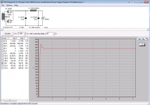
What's C4 value, and B+?
I can see a 47uF cap and a meter reading 438 volts in the picture.
I came across a used set of OTs and a PT. Does anyone know if these will work with 300b tubes?
EDCOR - CXSE25-3.75K (this seems right to me?)
EDCOR - XPWR008
The 300V on the PT is lower then recommended, but if I model it with PSUD it seems like it could work with a bit of tweaking? Also, the PT is only Center Tapped on the 300V - is that ok?
Thanks for the help!
EDCOR - CXSE25-3.75K (this seems right to me?)
EDCOR - XPWR008
The 300V on the PT is lower then recommended, but if I model it with PSUD it seems like it could work with a bit of tweaking? Also, the PT is only Center Tapped on the 300V - is that ok?
Thanks for the help!
Attachments
Last edited:
yes, 47uF cap and a meter reading 438 volts.
I changed to a 5U4 rectifier (I've got loads of these) and that helped a bit, with a 10uF, it reduced the voltage further down to 413v. Got no more lower value caps so will order more.
One quick other question, is my B- voltage OK at nearly 100v more negative?
Thanks for the help.
I changed to a 5U4 rectifier (I've got loads of these) and that helped a bit, with a 10uF, it reduced the voltage further down to 413v. Got no more lower value caps so will order more.
One quick other question, is my B- voltage OK at nearly 100v more negative?
Thanks for the help.
Last edited:
I came across a used set of OTs and a PT. Does anyone know if these will work with 300b tubes?
They will work. I have a 300-0-300 volt power transformer in my test amp and I get 370 to 390 volts of B+ depending on line voltage ans how much current I run. Get a choke with low DC resistance to make the most B+. I use a Triad C17-X. It's ugly so you have to hide it under the deck.
The 6.3 volt CT is not needed with 300B's.
I use a Triad C17-X. It's ugly so you have to hide it under the deck.
George,
Is that a typo? Shouldn't it be Triad C-14X?
Is that a typo? Shouldn't it be Triad C-14X?
For most builders the C-14X is the best low cost choke. It does however have 200 ohms of DC resistance, which at about 200 mA total current, will drop about 40 volts of B+ voltage. With a 325-0-325 volt power transformer the B+ should be in the 375 to 400 volt range.
With a 300-0-300 volt power transformer the B+ will be in the 350 volt range, which works OK with 300B's and is close to WE's original 360 volt recommendation. Many builders prefer to run their 300B's near 400 volts, so swapping in a low DC resistance choke will boost the B+ voltage.
Compared to the C-14X , the C-17X has lower inductance which could increase hum, but it has far lower DCR at 40 ohms, which will increase the B+. 200 mA through the 40 ohm choke will only drop 8 volts, affording a 32 volt increase over the C-14X.
I have run my amp with a Hammond 372HX (same 300-0-300 ACV @200 mA) and a Triad C-17X. I get 375 volts with 2A3's cranked to 70 Ma each (current similar to 300B's). I hear no hum with headphones wired directly across the speaker leads.
They will work. I have a 300-0-300 volt power transformer in my test amp and I get 370 to 390 volts of B+ depending on line voltage ans how much current I run. Get a choke with low DC resistance to make the most B+. I use a Triad C17-X. It's ugly so you have to hide it under the deck.
The 6.3 volt CT is not needed with 300B's.
Thanks for the detailed response George -- much appreciated!
Another TSEII Up and Running...
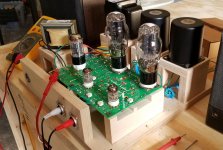
Received my board in the mail yesterday, just in time for the weekend. Spent most of last evening soldering, checking, and re-checking. Today was all about the woodworking required to put it all together as a functioning 3-D mock-up of the final design.
Oh, boy is this a nice amp! Right now it's playing through an old pair of JBL62 bookshelf speakers (89 dB), and there's plenty of volume. Sounds crisp and clean, too - not exactly what I expected from small SET like this. I'll let the voltages stabilize before taking it upstairs and hooking it up to the main system, but I'm already expecting to be in for a real treat.
I'm running a pair of sino 2A3's (the cheap ones with the 300B-esque plate) at ~50 mA each. The OPTs are 10 W James 2.5 k / 3.5 k units; I'm currently using the 3.5 k taps. The B+ is a little hot at ~308 VDC as measured at the plates; this is likely because of the Hammond 159S choke, which puts only about 65 Ohms between the filter caps.
Thanks to George for such a good-sounding and elegant design. It's a keeper for sure. Woo-Hoo!
I'll post some more pictures when it's more properly attired...
Attachments
")
I'm mostly interested in the proper way of grounding
I was wondering this as well and also wasn't totally sure. At first I just had the HV center tap connected to one of the T1-red/yellow ground pads, but this was a bit unstable with this and not as "clear" sound as I would have expected.
I measured the voltage between the ground pad and the mains earth WITHOUT the mains earth connected and there was several 10s of voltage difference, which I didn't think was correct.
I then attached a ground wire from the mains in earth terminal to the other T1-red/yellow ground pad and this made all the difference and much better and clearer sound. I'm guessing that the mains ground should also be connected to the circuit board as well. I also have it connected to the -ve speaker out terminals and all metal chassis bits I have in a star pattern.
is there a wiring guide for the TSE similar to the one for the SSE?
Not yet, I still need to make it.
I then attached a ground wire from the mains in earth terminal to the other T1-red/yellow ground pad
The T1-red/yellow ground pad IS the star ground point for the PC board. It is connected to the negative ends of C4 and C5 by a fat trace. All other subsection grounds are returned to the same point, the negative end of C5. Use the spare hole in that connector for the a wire to the ground pin on the power inlet, and the cold side of the speaker terminals.
If the ground side of the input connectors make contact with the chassis, then the chassis will be grounded through the input connector. If the connectors are isolated, then ground the chassis to the T1-red/yellow ground pad. Do not do both, as this will create a ground loop.
Before calling it done, use an ohmmeter to verify that the chassis, input connectors, and the ground on the power cord are all connected to each other. Check the metal housings on the transformers too. I have seen them short, usually where the wires enter the end bells. A blown fuse is preferred over a transformer with 400 volts on its conductive case.
I know that this wasn't supposed to happen, but I am currently out of TSE-II boards. I ordered a new batch about 3 weeks ago as the first batch was dwindling.
When the box appeared on my front porch I was surprised to find over a year's supply of SSE boards instead of TSE-II's. It is still not clear how this happened, or who's fault it was, but the board house is making me some TSE-II's. I asked for a rush on at least some of them. Best guess is ship out to me on Friday.
When the box appeared on my front porch I was surprised to find over a year's supply of SSE boards instead of TSE-II's. It is still not clear how this happened, or who's fault it was, but the board house is making me some TSE-II's. I asked for a rush on at least some of them. Best guess is ship out to me on Friday.
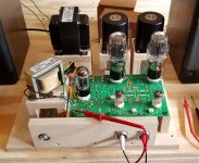
Thanks, itsikhefez. I call it the "Borg" method - a relatively quick and dirty way to determine whether or not a particular layout will work, both physically and electrically. It also enhances safety because the heavy stuff is fastened down and most of the flying leads are tucked away....nice test layout there.
In this case I found that a 12" x 12" x 3" (305 mm x 305 mm x 76 mm) enclosure would work for the basic amplifier. However, I want to add some goodies like a volume control, etc. - and that means I'll need to add another 1" (25.4 mm) to the cabinet thickness for added cooling, shielding and working space. As a bonus, it even works out better aesthetically.
All of this for ~10 USD worth of baltic birch ply. What's not to like?
I'm glad I listened to my gut and ordered when I did. For anyone contemplating purchasing a board, just do it. Seriously.I know that this wasn't supposed to happen, but I am currently out of TSE-II boards.
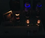
Mine's been a functioning amplifier for 48 hours, and I don't think I've been any happier with the outcome of a build. This is just a really nice little amp. Right now I have it connected to a pair of 100 dB Klipsch KLF-20s, and this combination seems to work well in the main listening area (an acoustically-active 26' x 17' room with a 16' vaulted ceiling).
I really have a hard time believing all of this sound is coming out of just a pair of 2A3s.
Nicely done, Sir!
Attachments
Last edited:
The dimension info is very useful for me.
By adding 1" to the thickness, did you mean a 4" tall cabinet?
I'm building this as a headphone amp, so don't want it to be too oversized. My Bottlehead Mainline top plate was 12" x 12", and the wood cabinet surrounding it was 3/4" thick and 3.5" tall.
That size was pretty perfect for me, but I have a feeling that it will be too tight with the ElectraPrint OPT's, Hammond 370EX, choke and motor run cap. Although, I won't have speaker outs, just a volume pot and headphone jack on the front, so maybe it can work.
BTW, someone here mentioned ordering from Arrow. I have to second that recommendation. They are offering free shipping for orders 50+ and a 10% discount for new accounts.
I ordered the Hammond PT, xhoke, and all the other big items from them. Free shipping was 2 day express with FedEx... pretty crazy actually.
This really helped reduce the shipping cost from my second order from Mouser.
Yes, built using the usual method of sandwiching wooden sides between two top and bottom plates. All of the big stuff like transformers and the like are to be mounted on top. I'm figuring for an overall height of maybe 8" (203 mm) max.By adding 1" to the thickness, did you mean a 4" tall cabinet?
This amp will have the smallest footprint of any I've built so far. It's a tight squeeze, especially when you factor in the distances required to prevent the transformers from absorbing too much radiant heat from the power tubes. I'm helped somewhat by the relatively small size of those James OPTs, but yours might be a bigger challenge because of the larger footprint of the ElectraPrints.
That's why I built the experimental setup first. It showed me I can have that 12 x 12 footprint without inducing unwanted noise or cooking my OPTs. It also showed me that that Hammond transformer runs unbearably hot, for me at least. I may still purchase the 300-series version - or just bite the bullet and get the Edcor equivalent. Considering Hammond's p***-poor fit and finish (irregular laminations, spray paint, melted leads, etc.), the Edcors are probably worth the wait.
Last edited:
Kilokat made a really nice front panel express top mounting plate
https://www.diyaudio.com/forums/tubelab/157491-pictures-tubelab-amp-48.html#post5787985
But it was based on the original TSE, so would need changes for the TSE II.
Also, assembly would be much easier with this type of setup, with everything on the top plate. I learned the hard way its a pain when everything is not mounted to the top plate.
Randy
I've admired that amp since I first saw it, and briefly considered that arrangement for mine. Ultimately I decided against it because it just didn't fit in with my goal, which was to go up instead of out. I'm attempting to achieve a sort of "Googie" effect for maximum WAF. So far she thinks it's "cute", which is a good sign.
I am thinking about how to do the top plate. I won't likely go the FPE route since I'm a fairly decent hobby machinist with access to a milling machine.
I am thinking about how to do the top plate. I won't likely go the FPE route since I'm a fairly decent hobby machinist with access to a milling machine.
Last edited:
- Home
- More Vendors...
- Tubelab
- After a 14 year run, the TSE must DIE!