The new board is 8.5 inches by 5.5 inches.
Thanks George,
Here is my build so far with the paper pcb the correct size, so I have more than enough room. I'm just waiting for the illuminated on/off switch to arrive that will go in the hole on the right hand side of the front panel and then will wire up as much as I can. This is my first build that isn't from a kit or recapping old amplifiers/radios. As such I'm prototyping it on a wooden board before I build my first chassis. I love the green Russian k72-11s but at 2.8lb and the size (over 7 1/2 inches long), I might have to change to smaller coupling caps when I make the final chassis.
Attachments
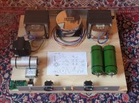
Here is my build so far with the paper pcb the correct size
Here is a new piece of paper with the correct picture. Verify that it prints out at 8.5 X 5.5 inches. Some printers are off by a little.
I might have to change to smaller coupling caps
Those are the biggest coupling caps I have ever seen......seriously, I don't know what their value is, but there is such a thing as too big. The original TSE had anywhere from 100K to 470K resistors installed for R15 and R26. I have increased this to 1 MEG for the TSE-II in order to boost the gain a little. This gives a 10 Hz corner frequency with a 0.1 uF coupling cap. Installing a really big cap would lower the corner frequency to the point where it takes too long for the bias to change when turning the pot. If your system has no low frequency roll off things like a warped record can make your speaker cones move....a lot! I learned this in my solid state days with a Carver 400 watt amp. In a tube amp it causes distortion due to OPT saturation.
I wouldn't use a cap much larger than 1 uF and reduce the value of R15 and R26 if you go that large. In this design the coupling cap works into a high impedance, the 1 meg resistor and a couple of pF in the mosfet. This makes minor imperfections in the coupling caps a non - issue. super expensive caps are really not needed, but you can use them if you prefer, just keep the value near 0.1uF
With the TSE-II hopefully available soon for purchase
The boards have been ordered. It usually takes about 3 weeks to get them even though they are made in Chicago.
it accommodates a 4-pin power tubes only. I built adapters for mine.
The board is laid out for a 4 pin socket. There isn't room to add additional sockets without compromising the design. The area along the rear of the board contains the large traces needed to carry 2.5 amps of filament current to the right most tube. A 2A3 needs 2.5 amps each. That precludes more screw connectors like those used for the OPT.
It is possible to build adapters for other tubes, and I made some to install 307A's in the original TSE board. It's also possible to run SHORT wires from the board to off board sockets, or just set the socket on top of the board and wire it up. The plate connection can be run directly from the OPT to the socket using the OPT's wire. One end of the grid stopper (R33 and R34) can be soldered into the board, and the other to the socket. One heater connection goes to ground, so that leaves only one wire to solder to the heater terminal of the socket on the board. I will make, and post some examples of this once I have the production boards at hand. A lot will depend on your individual chassis / cabinet design.
If you look at the enclosed printout of the board silkscreen you will see several ROUND circles. These are all mounting or ventilation holes. They are NOT electrically connected to anything. There are two OCTAGONAL holes under R36. These are to provide air flow to R36 and are connected to GROUND. They also provide a dual electrical path for the 2.5 amps needed for the right channel output tube. They should NOT be used for mounting unless non conductive hardware is used. The exposed metal around them can be used for a heater ground connection, but should not be connected to chassis ground to avoid a ground loop.
A lot of this will become more obvious once I have real boards and shoot a zillion pictures......and maybe a video build up or two.
Is it possible to provide the option to use octal power tubes like 6B4, or xLW6?
I have a bunch of both tubes too, so I will come up with a way to make the 6B4 work.......You could use the 26LW6, but they really don't like to run in triode mode. I blew 4 6LW6's in my original triode 6LW6 amp over a two year period before I dismantled it.
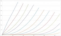
It is possible to run the 6WL6 in SE pentode mode, but that requires a screen supply and some feedback. There MAY be something new on the horizon that suits the LW6's much better. I have a prototype board of a P-P version with small tubes running. The simulation for the SE version looks very good, and the prototype was about halfway finished when the TSE filament regulators vanished overnight putting the TSE-II project on the top of the priority list. I have already called it the UNSET, since it works and sounds like a SET design, but contains NO triodes. The "triode" curves shown in the picture came from a small pentode sweep tube, a 6GF5. if it looks like a triode and sounds like a triode........
I'm holding onto my LW6's, and collecting more of them for two projects, a kilowatt push pull amp (500 WPC) and a big SE amp.
Are you are familiar with Pete Millett’s 50 watt mono block PCB
I have not seen the mono block version. I know where it came from though. I bought one of Petes original Engineers Amp boards when it appeared, and said that I would be disappointed if I didn't get at least 50 WPC from it. That turned out to be too easy. 50 WPC happened within a few days from building it, and 250 WPC flowed forth from it before I decided that that was about the limit. I wired both channels in parallel and saw 525 watts on the meter before hitting the kill switch. I decided that 125 WPC was about right for reliability and got there with the 6HJ5's. Pete is a bit more conservative than me. 250 WPC is definitely possible with a pair of some 6LW6's. 500 WPC will require 4 or 6 tubes per channel.
Attachments
[/URL]
Thank you for the updated schematic, it looks good!
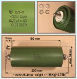
Just the physical size is large, the caps value are your recommended 0.22uF (I wouldn't arbitrarily use a totally different value), These are teflon caps rated at 1000v so that probably accounts for their size.
They were actually quite cheap, but I see are not selling that fast, at 50USD for a matched pair. Not sure if I can post ebay links, but if you are interested and search for "MATCHED PAIR Russian Teflon Capacitors K72-11" you will find them. I've attached a picture from the listing. (There's also a listing for unmatched k72-11s for 20USD each).
When you say you are thinking of building a big SE amp, were you referring to the UNSET amp? or another SE triode?
My ultimate goal is to build a SE amp that can give between 30 to 60 watts (A2) as 8 watts isn't really enough for the bass heavy electronic music I also like. I was originally thinking of using Russian GM-70s and adapting your 845 SE build to use the GM-70s. So I for one, would be very interested in your "big SE amp". This is a long term goal of mine that I wouldn't be starting for at least another year until after I've gained more experience.
Here is a new piece of paper with the correct picture.
...
I wouldn't use a cap much larger than 1 uF
...
I'm holding onto my LW6's, and collecting more of them for two projects, a kilowatt push pull amp (500 WPC) and a big SE amp.
Thank you for the updated schematic, it looks good!
Just the physical size is large, the caps value are your recommended 0.22uF (I wouldn't arbitrarily use a totally different value), These are teflon caps rated at 1000v so that probably accounts for their size.
They were actually quite cheap, but I see are not selling that fast, at 50USD for a matched pair. Not sure if I can post ebay links, but if you are interested and search for "MATCHED PAIR Russian Teflon Capacitors K72-11" you will find them. I've attached a picture from the listing. (There's also a listing for unmatched k72-11s for 20USD each).
When you say you are thinking of building a big SE amp, were you referring to the UNSET amp? or another SE triode?
My ultimate goal is to build a SE amp that can give between 30 to 60 watts (A2) as 8 watts isn't really enough for the bass heavy electronic music I also like. I was originally thinking of using Russian GM-70s and adapting your 845 SE build to use the GM-70s. So I for one, would be very interested in your "big SE amp". This is a long term goal of mine that I wouldn't be starting for at least another year until after I've gained more experience.
Attachments
Last edited:
Hi Francois,Are you are familiar with Pete Millett’s 50 watt mono block PCB.
Pete's got a lot of interesting projects there! What especially caught my eye was the microprocessor-controlled power supply part of his 813 single-ended triode amp, with its cool (in my opinion) LCD readout of values.
I might look deeper into this and see if I would be able to use it to control the power supply to the GM-70s in the potential GM-70 SE amp I would like to build in the future.
You'll be better off integrating an active subwoofer instead.[/URL]My ultimate goal is to build a SE amp that can give between 30 to 60 watts (A2) as 8 watts isn't really enough for the bass heavy electronic music I also like.
I'm very interested in building this as my next project. The new board sounds great and just what I'm looking for.
What output transformers are ideal? 5k or 3k primary impedance and 65, 80, or 100ma primary current. Speakers are 8ohm, 92db eff., and very easy to drive with no dips.
Also, is the parts list up to date? Any changes to run 300b? I was reading some old threads and they noted a number of changes to get the 300b running well with good numbers. I only have basic test equipment, so that would not be easy for me.
You'll be better off integrating an active subwoofer instead.
I thought of that but for the best quality I would need to get an active crossover, which I don't really want to. I have a 130 watt push pull amp that handles bass very well, so if the SE amp has problems I can use that. Nevertheless, I want a SE amp that can handle as good as possible bass, and then the push pull can take over if it has problems.
This amp has good bass, assuming you've got good efficient drivers in a well designed cabinet. (and good transformers, etc, etc)
But, I do have a little powered subwoofer in each corner of the room, too. The subs are set to quite low frequencies and to be honest, the audio quality at that level doesn't matter much.
I actually drive my subs through the speaker input, rather than the line level input (I've tried both). It's most definitely my full range speakers that are my limiting factor in bass.. not the amp itself.
Last edited:
God to know, The SE II I am building now I wont expect to handle electronic bass music but would be nice to have a reasonable bass. But a more powerful SE amp I plan to build in the future I hope it will be able to handle some electronic bass.This amp has good bass, assuming you've got good efficient drivers in a well designed cabinet.
The speakers I have now have a sensitivity of 96db/w/m and bass extension down to about 35 Hz after a bit of eq in JRiver.
Last edited:
I listen to electronic music all the time on my TSE. It's great!
I built Pete's 50 watt amp, too.. Really, they sound about the same, heh..
Both good designs.. Both have a full range of output.. Amps aren't supposed to sound like anything, and both designs succeed.
Due to speaker efficiency, both have about the same volume, too! But my push pull monoblocks are a little louder.
There is learning curve with active crossover but once you get through it, you won't go back to passive stuff. It's better for sound quality and it's flexible (for tweaking / fine tuning).I thought of that but for the best quality I would need to get an active crossover, which I don't really want to.
What are you guys talking about for active crossovers?
I got the miniDSP, and it's great for digital music, MP3, FLAC, etc... But I wouldn't put my records or other analog sources through it.. I think it looses some of the analog goodness.. (Although if you gave me a blind listening test, I don't know if I could really tell the difference.. It just seems wrong.. Analog record to analog phono amp, converted to digital and processed, then converted back to analog to the amps).
I got the miniDSP, and it's great for digital music, MP3, FLAC, etc... But I wouldn't put my records or other analog sources through it.. I think it looses some of the analog goodness.. (Although if you gave me a blind listening test, I don't know if I could really tell the difference.. It just seems wrong.. Analog record to analog phono amp, converted to digital and processed, then converted back to analog to the amps).
tse-ii available?
In a recent post, George said that he has ordered the boards and they will take about 3 weeks to arrive back, this was 2 weeks ago, so at least 1 more week.
- Home
- More Vendors...
- Tubelab
- After a 14 year run, the TSE must DIE!