TSE board. I hope there is at least 1 left.
Plenty left. I haven't counted lately but there is still an unopened 25 pack still on the shelf.
you can ship anything that fits in the Flat Rate box for the same price, regardless of weight. A couple lead bricks?......The maximum weight is listed as 70 pounds,
Waste postage on lead bricks? Maybe someone who casts their own bullets, but I prefer shipping bricks made from iron and copper.
Years ago I wanted to build a mega - power adjustable power supply. That exercise made my mail carrier very angry. Instead of delivering my mail I got a notice to pick my stuff up at the post office. It seems that a 1 KVA 480 volt to 120 volt industrial control transformer WILL fit into a medium flat rate box with styrofoam on all 6 sides, but the letter carrier couldn't pick up the box. I had two of those and one of the two big variacs that I bought off Ebay arrive at the post office the same day. The flat rate box is just the ticket for shipping big transformers......now if we could only get Edcor to use it.
US shippers can use the "flat rate boxes" which the US Postal service gives away for free, when you promise to ship by Priority Mail.
Yep. Those work great for shipping within the US. I seem to recall that the USPS will even deliver them by the bundle to your home/business for free! For shipping outside the US, Priority Mail is prohibitively expensive, however.
When I lived in the US, I found the $16.99/month subscription to Stamps.com well worth it. It allowed me to print First Class (including First Class International) postage at home, which is impossible through the USPS website (or at least it was at the time).
Tom
When I lived in the US, I found the $16.99/month subscription to Stamps.com well worth it. It allowed me to print First Class (including First Class International) postage at home, which is impossible through the USPS website (or at least it was at the time).
Tom
It's still impossible from the USPS website.....
t's still impossible from the USPS website.....
UH, I just printed the first class postage for a pair of PC boards being sent to the Netherlands this morning and I will take them to the post office tomorrow on my way back from the gym.
I have been printing first class international for several years from Welcome | USPS for years. I think that you may need to register and set up an account first, and log in for the option to appear.
I seem to recall that the USPS will even deliver them by the bundle to your home/business for free!
Yes, the priority mail envelopes come here for free. I order 100 of them at a time and they take about 10 days to arrive. I order first class mailers from Uline. They are not free, but are cheaper than the USPS mailers.
Not sure if this is the place to suggest it but I just ordered a Tubelab SE pcb and one of the first things I’ll be looking to do is install some sort of subwoofer output on the circuit. Provisions for an option such as this might be desirable in a redesign, perhaps something transformer-based on the input.
It happens that today I am in the second day of assembly of a SE board I bought two or three years ago. Life happened and I’m just now getting to it. Most of my thoughts have been shared by others but I do have a suggestion.
I understand the beauty and simplicity of having all the components mounted above the board and I may come to value that even more as I set the bias. Having said that, I will probably install all the caps underneath and I’d do the same with all of the solid state components were that possible (assuming I could resolve cooling). It’s just simpler for me to build a safe enclosure that way.
My suggestion would be a provision for that. Perhaps two pair of heat sink mounting holes for the TO3 devices and a two sets of pads for the regulator. One could even silk screen both side of the board.
Kudos on the assembly instructions online. And the safety page should be required reading.
Last edited:
Regarding the obsolete regulator ...
I was looking for parts for my recently acquired TSE board, and was wondering how to solve the regulator issue.
I saw that DigiKey still list around 800 units of the slightly lower spec version, which is restricted to 3.5 amps (part 425-2349-5-ND). Looking at the possible tubes I could use, as long as I steer clear from the 2.5v heaters then 3.5 amps should be no problem.
Looking at the board, if I cut one of the tracks for heater filament supply on the board, then there is the possibility to mount two of the 3.5 amp regulators as part of an off-board solution, with a separate regulator for each filament.
So there would seem to still be an open door for potential builders of this amplifier. Hoping my reasoning is correct!
Maybe a HD regulator be built of discrete parts that would work just as well or is there nothing suitable for that? Of course it would have to be on a separate little PCB or Perf. board.
There also might be a market for a fil. regulator PCB to sell?
How about the reg. in post #14 (2nd last ) and it's 7.5A. Might be best to use 1/CH & heatsink it it like jdrouin did.
Alternative Voltage Regulator for TSE
There also might be a market for a fil. regulator PCB to sell?
How about the reg. in post #14 (2nd last ) and it's 7.5A. Might be best to use 1/CH & heatsink it it like jdrouin did.
Alternative Voltage Regulator for TSE
The 7A version is available in large quantities from these 2 suppliers. 1st in Japan so you would think it's safe. 2nd Taiwan so?
Brokers, Distributors & Dealers
http://www.firstic.com/partrult.asp
Many 1000's in stock from these suppliers:
PQ5EV7 Price & Stock | DigiPart
Search | WIN SOURCE
Digikey and Mouser aren't the only suppliers and sure those chips are out of production, but for the amount of board sales and low price in quantity one could stock up.
There are other fil. reg pcb's for DHT tubes out there that could be used if need be.
I saw that DigiKey still list around 800 units of the slightly lower spec version, which is restricted to 3.5 amps
I have 10 of these on the way. The tracking number shows delivery for tomorrow, but no actual scan since shipment. A serious snowstorm may delay that a bit. We had 6 inches here today, and its still coming down.
I have one of the first ever commercial quality TSE boards on my workbench. It was one of two I built from the first batch of TSE PC boards I had made in 2005. I replaced the blown mosfet from an experiment gone wrong, and listened to it for several hours last night.
I will test the 3.5 amp chips in it with 45's and 300B's at various line voltages and conditions. On paper they should work, but I won't believe it until I test and compare everything to the 5 amp chip that's in the board. If they work there, then a 3.5 amp chip gets fittent into my Lexan TSE. That amp runs HOT due to it's cramped chassis with near zero ventilation. It is also home to the other one of the original TSE boards.
I also have several candidate regulator chips coming in the same Digikey order. None of these are pin compatible, and would require a board change. All will be tested!
I believe that it will work, and may order some, but I have never actually tried them. I don't remember WHY I didn't try them, but knowing me, 15 years ago when I designed the TSE, it was probably price. Why spend $6 when $3 works just as good?
After letting some, but not all, of the smoke out of my power transformer by dropping a nut on a live board, I'm set up for some regulator testing tomorrow. I have a variac wired into the primary of my still hot power transformer for dropout testing. The 5 amp chip that is in the board starts to pass ripple when the line voltage goes below 110 volts. I will test the other perspective chips against that benchmark, then look for ways to improve it.
My board is almost 15 years old, and its parts are about 18 years old. Maybe those power supply caps aren't what they used to be. Then maybe my 15 year old power transformer didn't like having it's 6.3 volt winding shorted long enough to melt the green wires together!
I have some of the 3.5 Amp Sharp parts, and 3 different versions of other possible replacements which would require a new board layout. I don't have any of the 7 amp parts to try though.
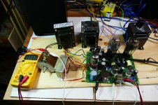
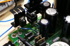
I set up a quick bench test system to evaluate regulator chips. Please do NOT duplicate my rather crude and unsafe test setup. There is exposed line and B+ voltage everywhere.
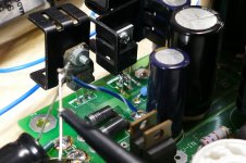
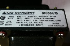
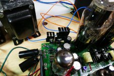
The picture shows a TSE board on a piece of plywood with a small Allied 6K56VG power transformer which is a good choice for a 45 board. There are a pair of Transcendar 3K ohm OPT's which were designed for a 300B amp, so I put the 8 ohm speakers on the 4 ohm tap for a 6K load, and a power supply choke robbed from a HP audio oscillator.
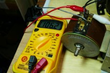
The tubes are 1930's vintage RCA 45's. The entire board is connected to a small variac with a DVM across it's output for applied line voltage measurements. A dual trace scope is used to monitor the raw DC voltage out of the filament rectifier and the DC voltage at the filament pin of the right most output tube. An iPAD is used for a source, and a pair of really inefficient Cerwin Vega HT satellite speakers are used for quiet listening.
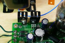
I removed the stock dual heat sink that is fitted to both the filament rectifier and regulator and fitted small individual heat sinks to each part. This makes swapping regulator chips a bit easier. Note the melted green wires caused by dropping a 4-40 nut from one of the heat sinks on to a live board. It landed right on the exposed leads on the left side of the diodes. Smoke ensued, then the middle green wire unsoldered itself and the amp kept right on playing!
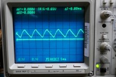
The amp was playing music while the line voltage was adjusted for the lowest line voltage that produced PURE DC at the tube heaters. Note the first picture of the scope screen. The vertical scale is 1 volt per box. The DC line (bottom trace) is at 2.45 volts, while the top trace shows 3.3 volts average with over a volt of ripple.
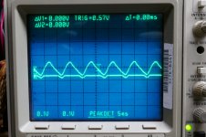
I then reduced the line voltage until ripple was seen on the tube filaments (second picture) and then turned the variac back up until the ripple just disappeared (the first picture) and recorded the voltage.
The voltage required for zero ripple with the 5 Amp Sharp chip was 114.1 volts. I installed the 3 amp Sharp chip and performed the same test again. The voltage was 114.4 volts. Slightly worse, but two identical chipps could have done the same thing. The voltage difference between the two traces is known as the dropout voltage, and both Sharp chips perform significantly better than the published spec.
This shows that the 3 amp Sharp chip will work in the TSE board. Obviously it will not power a pair of 2A3's (2.5 amps each) but 45's (1.5 amps each) and 300B's (1.2 amps each) should be fine.
The picture shows a TSE board on a piece of plywood with a small Allied 6K56VG power transformer which is a good choice for a 45 board. There are a pair of Transcendar 3K ohm OPT's which were designed for a 300B amp, so I put the 8 ohm speakers on the 4 ohm tap for a 6K load, and a power supply choke robbed from a HP audio oscillator.
The tubes are 1930's vintage RCA 45's. The entire board is connected to a small variac with a DVM across it's output for applied line voltage measurements. A dual trace scope is used to monitor the raw DC voltage out of the filament rectifier and the DC voltage at the filament pin of the right most output tube. An iPAD is used for a source, and a pair of really inefficient Cerwin Vega HT satellite speakers are used for quiet listening.
I removed the stock dual heat sink that is fitted to both the filament rectifier and regulator and fitted small individual heat sinks to each part. This makes swapping regulator chips a bit easier. Note the melted green wires caused by dropping a 4-40 nut from one of the heat sinks on to a live board. It landed right on the exposed leads on the left side of the diodes. Smoke ensued, then the middle green wire unsoldered itself and the amp kept right on playing!
The amp was playing music while the line voltage was adjusted for the lowest line voltage that produced PURE DC at the tube heaters. Note the first picture of the scope screen. The vertical scale is 1 volt per box. The DC line (bottom trace) is at 2.45 volts, while the top trace shows 3.3 volts average with over a volt of ripple.
I then reduced the line voltage until ripple was seen on the tube filaments (second picture) and then turned the variac back up until the ripple just disappeared (the first picture) and recorded the voltage.
The voltage required for zero ripple with the 5 Amp Sharp chip was 114.1 volts. I installed the 3 amp Sharp chip and performed the same test again. The voltage was 114.4 volts. Slightly worse, but two identical chipps could have done the same thing. The voltage difference between the two traces is known as the dropout voltage, and both Sharp chips perform significantly better than the published spec.
This shows that the 3 amp Sharp chip will work in the TSE board. Obviously it will not power a pair of 2A3's (2.5 amps each) but 45's (1.5 amps each) and 300B's (1.2 amps each) should be fine.
Attachments
Just saw this thread.
I built the SSE but not the SE. I’ve always considered building a 300B based tube amp but never did. Whether the new design incorporates one or two boards on the same footprint (chassis) does not make a difference to me. What I would not build is mono-blocks.
I built the SSE but not the SE. I’ve always considered building a 300B based tube amp but never did. Whether the new design incorporates one or two boards on the same footprint (chassis) does not make a difference to me. What I would not build is mono-blocks.
Later on last night I was preparing to rip the Sharp from the board to figure out how to test some possible replacements when I decided to replace C1. It is about 15 years old and been in this board since day 1. The board has been used as a test mule for dozens of experiments, so maybe the cap was less than perfect. 1 volt of ripple on a 3.5 volt supply seems a bit much, so I dug through my box, and found.....the exact package the original cap came out of in Feb 2005. There were 8 caps left in a package of 10, and I have two boards.
I put a new 2005 vintage cap in place of a well used 2005 vintage cap, and it did make an improvement. The line voltage for dropout went down to 111.1 volts. I turned everything off, and revisited the amp this morning. The voltage needed for dropout was now 109.9, virtually the same number.....
If one cap is good, two must be better, right? How many of us have Aux caps on our SSE's and TSE's? So does two caps work better than one, you bet! Voltage for dropout is now 106.2 volts.
Now it's time to rip the board apart. I have 3 different regulators from Microchip / Micrel that all share the same pinout. They are the only parts I can find in a leaded package with a sub 1 volt dropout.
It turns out that with some creative lead bending, you can fit these chips into the existing board without cutting any traces or running any jumpers. I stuffed the best ($8) chip into the board and plugged it in. There was 2.52 volts in the tube socket, without any output tubes, so I popped in my 45's and cranked up the tunes.
It plays fine, but the dropout voltage went from 106.2 (two caps) to 107.8, a considerable loss of ground. If this is the best chip, what will the cheap chips do? I don't know yet....I'm going to beat on this one a bit.....OK, a lot. For 8 bucks each it should be bullet proof, and maybe even conjure up some audiophool magic!
Attachments
Whether the new design incorporates one or two boards on the same footprint (chassis) does not make a difference to me
It is beginning to look like I can make some minor changes to the existing TSE board to fit a different regulator, a bigger cap in the filament supply, and maybe some other minor changes and keep the TSE pretty much as it is. After all several hundred have been built (best guess), and people like the amp.
Then We can discuss some modular amp designs for DHT's and other fun tubes.
There is one question that keeps coming back up. The TSE was originally conceived as a compact sized amp intended for 45 tubes. 45's have become scarce and expensive, so most TSE's get built with 300B's. Some fat "300B's" almost touch each other. Does it make sense to stretch the board a bit to put more space between the output tubes? Doing this would render existing top plate templates useless, and may raise the cost of the PCB a few bucks.
I know that there was at least one builder that made a Front Panel Express top plate for the TSE. Occasionally someone buys 5 or more boards at a time, presumably they have some pre-made panel. Would a board stretch be a problem for anyone, or would it make life easier?
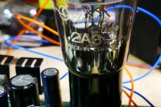
I was thinking about how to torture test the new regulator when a reader asked some questions about a TSE for 2A3's. Suddenly the light went on.....What would happen if I simply stuffed a pair of 2A3's into this amp as it site. Would the remaining smoke get set free from my power transformer when I ask it to give me about 6 amps from its 3.5 amp heater winding? What would the Microchip regulator do when it looks at the near dead short presented by a pair of cold 2A3's. Well there is only one way to find out....plug them in!
When the plug hit the wall outlet there was a thud from the transformer. The filament voltage moved up to about 1.5 volts then slowly climbed to about 2.2 volts and stayed there. My variac was still set at the same place where I got 107.8 volts with 45's, but now I'm only getting 105 something, so crank the variac up full, 122 volts (its cold outside). The filament voltage levels off at 2.51 volts, and music plays. It takes 119.5 volts to keep the regulator out of dropout, but my 6.3 volt winding is only making 6.0 volts.....and this IS a Hammond built transformer(notorious for too much voltage).
If one cap was good, and two was better, lets try THREE! Bingo, The board was happy dropout voltage was 112.3 volts. I put the speakers on the 8 ohm taps, set the bias for 60 mA (again sucking about 140 mA from a 120 mA HV winding) and listened to some good sounding music......for about 5 minutes, then silence.
I suspected blown parts, but the Microchip had simply shut down. I had used the tiny little heat sink shown in the previous thread. I simply screwed the original double heat sink and the tiny new heat sink together and used that. The amp played all day. Within about an hour the power transformer got too hot to touch, but after about 8 hours of stress, no smoke was released.
I still haven't tested 300B's, and I want to try the 2A3's with a real power transformer. I dug through my collection and found a Hammond 372HX still in its box, never used. This will feed the 2A3's too much B+, but who am I, Captain Red Plate?
Attachments

")
- Home
- More Vendors...
- Tubelab
- After a 14 year run, the TSE must DIE!