I still have a negative voltage reading after I install the rectifier tube which is a GZ34. I took a picture but I can't figure out how to post it. The B- reading is a positive voltage.
So the B+ reading is negative and the B- reading is positive? You're probably fine... It just sounds like your meter probes are flip-flopped. For both meters, reverse where you're connecting the red and black probes.
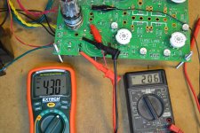
I am now to the step where I put in the 5842 tubes. I've attached the multimeters to C9 and C11 and ground. Right side (VR9) gives 174 volts with a little adjustment but left side (VR20) shows only 8 volts and does not change when I turn the Pot.
Switched tubes, no diff.
Switched multimeters, no diff.
replaced R20, no diff.
Any suggestions?
Switched tubes, no diff.
Switched multimeters, no diff.
replaced R20, no diff.
Any suggestions?
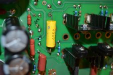
Looks like a burn mark from your soldering iron. Happens frequently when components are close to each other and you touch any part of the soldering iron to the plastic (polyester, etc) caps. Only way to find out if the component is bad is to remove and test with the multimeter.
You might check the variable resistor to see if you overheated it? Check the resistance with your multimeter.
You might check the variable resistor to see if you overheated it? Check the resistance with your multimeter.
Could this make for a bad cap?
It's possible. Unsolder one end of it, or remove it completely, and see if the adjustment works. If so, the cap is toast.
Note that the amp should adjust just fine without the cap, but you will get no sound in that channel without it.
Could I use the cap out of that as a replacement?
Yes, if it's not damaged. Even a brief touch with a soldering iron can completely short out a cap since they are made from very thin plastic rolled up.
I would test the voltage with no cap to be sure that the cap is really the problem.
After I put in the rectifier tube I have a B+ of -427 Volts. B+ should be 350 volts.
It should be a positive voltage if your black meter lead is on ground. Over 400 volts is normal if there are no output tubes in the amp. The voltage will come down as the output tubes are biased up.
I could really use some help/opinions on a problem I'm having. Recap: I am building a SE with 45 tubes for headphones. I have the whole amp wired up outside of a case and playing music, but I am hearing a 120 hz hum coming through my headphones. The hum does not change with volume control. I cannot for the life of me figure out where it's coming from or how to fix it.
OPTs are electraprint. 5k primary with 32 ohm secondary (it also has 120 ohm secondary, but I haven't tried it yet). PT is from transcendar. 265-0-265 @ 130mA, 6.3V CT @ 4A, 5V @ 3A
Here are the things I've tried so far:
- Different output and rectifier tubes.
- Different outlets in different circuits in my apartment.
- Triple checked that PT, OPTs, auxiliary cap, input RCAs, and volume are all grounded.
- Signal and PT wiring are separated.
- Tried doubling the capacitance of C7 (it was suggested that the hum may be coming through the bias line and doubling this cap would help. It did not.).
- Tried lifting the PT off the table to rule out silly things like vibrations.
- Tried many PSU filter combinations
- CLC (original setup) (47uF -> 40H 480 ohm -> 150uF)
- CLRC (47uF -> 10H 155 ohm -> 270 ohm -> 150uF)
- CLCLC (47uF -> 40H 480 ohm -> 85uF -> 10H 155 ohm -> 150uF)
(From here, it was suggested that increasing the size of the PSU and using smaller, more appropriate (higher) mA rated chokes would help. It definitely decreased the ripple in PSUD, but the hum was the same)
- CLCLC (47uF -> 10H 155 ohm -> 85uF -> 2.5H 43 ohm -> 150uF)
- CLCLC (47uF -> 10H 155 ohm -> 85uF -> 2.5H 43 ohm -> 710uF)
- CLCLC (47uF -> 10H 155 ohm -> 820uF -> 2.5H 43 ohm -> 710uF)
Every iteration had just about the same amount of hum. If there were any differences in hum volume, they were very minute or I just imagined them. In the last few filter iterations, PSUD was reporting below 100uV (and even as small as 7uV ripple). That should be way low enough to not hear hum. This makes me think it may not be a B+ ripple problem, but I could be wrong.
It's worth noting that I can hear a little bit of the same 120 hz hum coming from the PT itself. Is it possible that the mechanical PT noise is making it into my headphones? Everything I've read online says that mechanical hum shouldn't affect the output...
Long post, but I wanted to give as much information as possible. Any suggestions would be appreciated.
Did you switch out the 5842 tubes?
Not yet. That was the last idea I had. Don't have any extras on hand at the moment. Though the hum is equally present in both channels. So unless both 5842's are equally bad, I'm not sure those are the culprit. I'll buy some extras and try it out. If that doesn't work, then I am officially out of ideas.
Hello
I'm far from being especially knowledgeable with this stuff
But IF you are still doing the non-standard tube layout you were talking about in post 747, that could be contributing to your hum issues
Power transformer – Rectifier – reservoir cap loops are the “rippley-est” power loop on a tube amp I think, and keeping that loop contained, small and away from the driver circuit is important
http://www.valvewizard.co.uk/Grounding.pdf from the Valve wizard site has some good info on this
Also, the 5Vac going to the “off board” rectifier needs to be well dressed and kept away from sensitive circuits (Drivers)
If you haven’t done the non-standard layout in post 747 I haven’t a clue I’m afraid
Perhaps some pics would help?
Good luck
- Home
- More Vendors...
- Tubelab
- After a 14 year run, the TSE must DIE!