Really hot to touch those Q1, Q2, IC1, IC2 in my TSE-1. I measure temp around 170+ F.Good advice from hobbyamp.
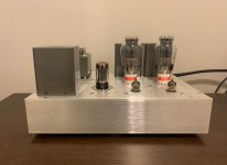
I installed the stock heatsink. It gets quite hot when running 2A3s, and while I'm sure it's up to the task short term I'll probably install something beefier at some point in the near future. The extra thermal mass can't hurt.
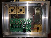
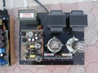
I'm wrapping up my second TSE and would like a sanity check on the grounding / safety of my work.
- Chassis is raw aluminum (not anodized)
- IEC inlet ground pin connected to chassis.
- Input RCA's are isolated from chassis and connected directly to the PCB (not pictured)
- PCB is connected to the chassis through the star ground terminal
- Both binding posts (-) are connected to the same screw
- The ISO opt and choke enclosures are fully painted, but on the other hand are screwed from underneath into the chassis. Do people scrape off paint on the bottom of these potted transformers?
All wiring is 19ga (kimber tcss)
Attachments
Thanks!
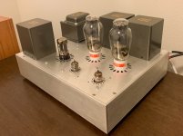
So far sounds very good but I have only listened briefly and there are many moving parts in my system.
I'm using it with a Schiit Saga for remote volume control which is new to me (temporarily, until I build something in its place).
I still need to put the 80uF cap on the PS and run some FR and THD measurements with ARTA for sanity check that everything is working as expected.
Attachments
I will make such a list as I begin building up some more TSE-II boards. Unfortunately there was a long period of time when I didn't build anything. I still have a couple of complete TSE boards from the initial build in 2006 that I never used, so I haven't built any TSE boards in a long time. I keep them around for testing alternative parts when necessary.
Not much needs changing except for the mosfets.
Hi George. Did you get around to creating a list of Tubelab recommended replacement mosfets for the original TSE? I am about to embark on the build, and it would be great to have that. Thanks!
Hi George. Did you get around to creating a list of Tubelab recommended replacement mosfets for the original TSE? I am about to embark on the build, and it would be great to have that. Thanks!
Hi, you can use the MosFets of the latest design (TSE-II) and vice versa.
On my TSE-II I'm using 2SK2700s.
Hi, you can use the MosFets of the latest design (TSE-II) and vice versa.
On my TSE-II I'm using 2SK2700s.
Thanks for that, I will check the mosfets used in the TSE-II.
Last edited:
The TSE and TSE-II have the same mosfet drive circuit, and can use the same fets. The TSE-II runs them at a lower voltage to reduce heat.
The 2SK2700's have been extinct for years. Some of the parts seen on the web are likely fake.
In today's constantly evolving world of electronics and parts a new part can be introduced, and be extinct in a year or two if it doesn't find a place in a high volume product.
The part that I have been using and recommending has been the On Semi NDF04N60Z, but it has vanished from the face of the planet.
The last two TSE-II boards I built have used the STF3LN80K5 part from ST microelectronics. They work fine and are in stock my the thousands at Digikey and Mouser....for now.
Hi George,The TSE and TSE-II have the same mosfet drive circuit, and can use the same fets. The TSE-II runs them at a lower voltage to reduce heat.
The 2SK2700's have been extinct for years. Some of the parts seen on the web are likely fake.
In today's constantly evolving world of electronics and parts a new part can be introduced, and be extinct in a year or two if it doesn't find a place in a high volume product.
The part that I have been using and recommending has been the On Semi NDF04N60Z, but it has vanished from the face of the planet.
The last two TSE-II boards I built have used the STF3LN80K5 part from ST microelectronics. They work fine and are in stock my the thousands at Digikey and Mouser....for now.
Is is OK to convert the TSE-1 to lower the voltage to 150V towards the mosfet ? My Q1/Q2 are off board and planning to lower the voltage by putting (in between) C15, R36, C14, and D6, and feed the voltage to Q1 Q2, in this way B+ is not directly to mosfet. In short, I am thinking disconnect cut this power wire towards mosfet then put it in series these 4 parts that will drop voltage by 200V !!! Less heat. My right channel in TSE-1 all of a sudden just fried both mosfet and the CCS and the grid resistor.
Is is OK to convert the TSE-1 to lower the voltage to 150V towards the mosfet ?
Yes, In fact that option was actually designed into the original TSE board. There is a jumper on the top side of the board between R34 and R18 that connects BPLUS to DRV_B+. If that jumper is not in place, a positive supply of 100 to 200 volts can be wired to the DRV_B+ pad and the mosfets will be much cooler.
You can also remove the D2 and D3 diodes, jumper R6, and provide a negative supply into the V-IN pad near the diodes. That gets rid of the heat from R6.
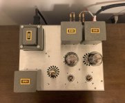
I originally used these boards as drivers for bigger amps. I used a small 120 to 230 VCT isolation transformer, 4 diodes and 2 caps to make a small +/- 150 volt supply in a manner similar to many solid state amps today, and ran the mosfets on this supply. 30 mA or so is plenty.
One of the first hand made TSE board prototypes was used in this 845 SE amplifier. You may notice that there is no connection to for the power transformer's HV or 5 volt windings and no rectifier tube. The B+, +150, and -150 volt supplies are all wired to the board from the amplifier's power supply chassis. I left those hooks in the final board design, but only 3 or 4 people ever used them, so they were removed for the TSE-II and the dropping resistor / Zener added.
Attachments
HV delay softstart or like
Hello all here")
So my TSEII is working, and when i do some listening on my bench, i was wondering if any delay circuit would be any good?
There are lot's of articles around out there, and i therefore have some quistions regarding this.
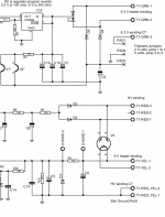
In schematic i see the two heater windings (6.3 & 5.0) connected to T1-GRN-1/2 & T1-YEL-1/2.
If power is applied two those first and after say 60sec. the HV is applied to T1-RED-3/1 then the heaters would be heated up before B+ will come up.
Does anyone here use this on theyr'e TSE's ? - is it a good idea ?
One thing more, if this is good i suppose that the HV centertab should be connected all the time and not delayed ?
Rgds; Jesper.
Hello all here
So my TSEII is working, and when i do some listening on my bench, i was wondering if any delay circuit would be any good?
There are lot's of articles around out there, and i therefore have some quistions regarding this.
In schematic i see the two heater windings (6.3 & 5.0) connected to T1-GRN-1/2 & T1-YEL-1/2.
If power is applied two those first and after say 60sec. the HV is applied to T1-RED-3/1 then the heaters would be heated up before B+ will come up.
Does anyone here use this on theyr'e TSE's ? - is it a good idea ?
One thing more, if this is good i suppose that the HV centertab should be connected all the time and not delayed ?
Rgds; Jesper.
Attachments
Hello all here
So my TSEII is working, and when i do some listening on my bench, i was wondering if any delay circuit would be any good?
There are lot's of articles around out there, and i therefore have some quistions regarding this.
In schematic i see the two heater windings (6.3 & 5.0) connected to T1-GRN-1/2 & T1-YEL-1/2.
If power is applied two those first and after say 60sec. the HV is applied to T1-RED-3/1 then the heaters would be heated up before B+ will come up.
Does anyone here use this on theyr'e TSE's ? - is it a good idea ?
One thing more, if this is good i suppose that the HV centertab should be connected all the time and not delayed ?
Rgds; Jesper.
Hi Jesper,
the delay is already implemented, it is the GZ34 tube rectifier, which causes the HV-supply to increase slowly.
HV-supply too high?
If you find out, that your HV-suppy is too high, besides lowering the value of C4, you could also try another rectifier which causes a higher voltage drop. I'm using the 5U4GB, which can be found NOS (even in Germany) at moderate prices.
The use of the 5U4GB has two disadvantages:
The filament draws 3 A (make sure your transformer can deliver this current!).
Because this rectifier is directly heated, the HV-startup delay is significantly reduced.
My current setup:
Transformer: Hammond 370HX; C4 = 22 µF (PP motor run cap); 5U4G, choke 10 H (0,2 A); C5 = 150 µF ....results in 270 V (HV); operating point of the JJ 2A3-40 is set to 55 mA.
Hi Jesper,
the delay is already implemented, it is the GZ34 tube rectifier, which causes the HV-supply to increase slowly.
Thanks...
Yes, i see that the rectifier are making delayed startup.. - But do we still benefit of an delayed HV ?
Jesper.
Thanks...
Yes, i see that the rectifier are making delayed startup.. - But do we still benefit of an delayed HV ?
Jesper.
Hi Jesper,
please connect a DVM across R30 set to V-DC and switch on your amplifier,
find out what happens!
Hi Jesper,
please connect a DVM across R30 set to V-DC and switch on your amplifier,
find out what happens!
Yep... B+ is slowly rising
But my thoughts was that more time could be even better, but ofcause the slowrise is nearly as good as using a variac on it i see, thanks for clearing it out for me
So i stick with a softstart build i am gonna make now.
Jesper.
One thing more, if this is good i suppose that the HV centertab should be connected all the time and not delayed ?
Since the TSE and TSE-II implement a bipolar supply with unequal current draw, lifting the CT or delaying it could have unpredictable results depending on tube warmup time. This could be seen as a positive voltage on the negative supply and not a good idea.
Yep... B+ is slowly rising...But my thoughts was that more time could be even better
The warm up time of a 45 or 300B is still faster than a 5U4 since there is more thermal mass in the 5U4's filament. There are possibly some 2A3's out there that are slow, but this is not generally a problem.
Slowly turning up the input voltage on a Variac allows all supplies to come up at roughly the same time. The TSE and TSE-II use a tube rectifier for B+ and a solid state rectifier for B- to insure that excess negative bias is there BEFORE the output tubes are warm so that they are cutoff during the first few seconds of conduction. The B- stays pretty far negative until the B+ comes up and starts pulling the grid bias more positive.
Hello all here
So my TSEII is working, and when i do some listening on my bench, i was wondering if any delay circuit would be any good?
There are lot's of articles around out there, and i therefore have some quistions regarding this.
In schematic i see the two heater windings (6.3 & 5.0) connected to T1-GRN-1/2 & T1-YEL-1/2.
If power is applied two those first and after say 60sec. the HV is applied to T1-RED-3/1 then the heaters would be heated up before B+ will come up.
Does anyone here use this on theyr'e TSE's ? - is it a good idea ?
One thing more, if this is good i suppose that the HV centertab should be connected all the time and not delayed ?
Rgds; Jesper.
A very intelligent friend of mine and well known person in tube amps once told me these about Cathode Stripping..
"It happens with specific tubes like the 6AS7’s, 6080’s, 6336’s the regulated power supply pass tubes are famous for it. They need preheating before plate current is run on them. These were never used in TV’s or audio, just power supplies until they got used for OTL’s, then it happened with the one’s that did not know about this condition, they just did not read the tube manuals, that do indicate this condition.
So, once an audiophile finds this out he then gets on line and thinks he has a cure for all the world’s tubes of cathode stripping problems!! He tells everyone to preheat ALL tubes, or leave them on or whatever goes on in there little minds.
This condition only exists with the pass tubes where the cathodes are very big and very close, to the plates".
- Home
- More Vendors...
- Tubelab
- After a 14 year run, the TSE must DIE!